
Introduction
This guide will provide you with the bare minimum needed to create shapes and extrude them in SolidWorks. Concepts/commands covered will include creating 2D shapes, dimensioning them, extruding them, and making cuts. The end goal is to have an .STL file for 3D printing. The tutorial is based on a component used in the DAMNED project.
-
-
Launch SolidWorks from any computer in the engineering buildings. You may also install it on your personal Windows machine by following the instructions here.
-
The basic idea in SolidWorks is to create a 2D shape (a sketch), add dimensions to it, and then extrude it. In other words you "pull" the 2D shape into a third dimension and give it depth.
-
Once you have a basic 3D shape then you can add additional 2D shapes on to it and further extrude these.
-
Alternatively, you can add a 2D shape onto a 3D part and use the 2D shape to create a cut.
-
There are many more things you can do in SolidWorks, but for the purposes of this tutorial that summarizes everything.
-
-
-
After launching SolidWorks, begin by creating a new part.
-
Once you have clicked OK to create a new part, be sure to choose metric units of measurement (MMGS) in the bottom right corner of the screen as shown here in green.
-
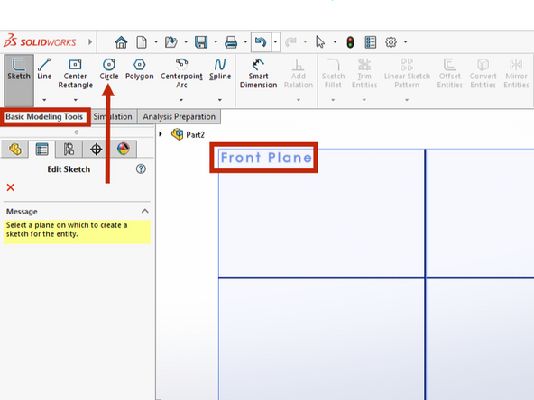
Create a center circle by clicking the Circle button within the Basic Modeling Tools tab.
-
Choose to create your sketch in the Front Plane by hovering your mouse over the correct plane until it highlights orange, then left clicking.
-
Click the origin of the sketch (small red axes near the center of the screen) to anchor the center of your circle there.
-
Move your pointer out away from the center of the circle. Create a circle of arbitrary radius by clicking again.
-
Rotating the scroll wheel of your mouse will zoom in or out on the drawing.
When I opened solid works it automatically defaulted to the metric system (MMGS).
Jack Casturo - Resolved on Release Reply
-
-
-
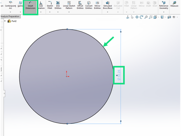
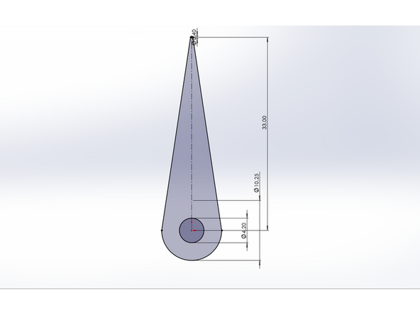
Click on the Smart Dimension button and then click on the edge of the circle you just drew. Drag the dimension out and click to anchor it. A pop up box will appear and allow you to enter a diameter value. Enter 10.25.
-
This circle will be the outside of the motor shaft extension. Let's view it from the top plane to make it easier to see.
There is a very little text there says Top. Sometimes is would shown when you orientate the screen to some of the surfaces. Look at the ones that have a label and find the surface or view you want to see.
Yuhe Zhang - Resolved on Release Reply
I like how easy it is on the program to change the radius of the circle and that the tutorial outlines this. This is especially helpful because even if you get the counter to displace the right value for your radius when you’re first making the circle, it displaces a rounded value.
Katelyn Shakir - Resolved on Release Reply
-
-
-
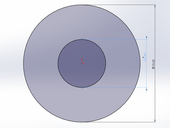
Now add a second, concentric circle inside of the first. This second circle should have a diameter of 4.5.
-
-
-
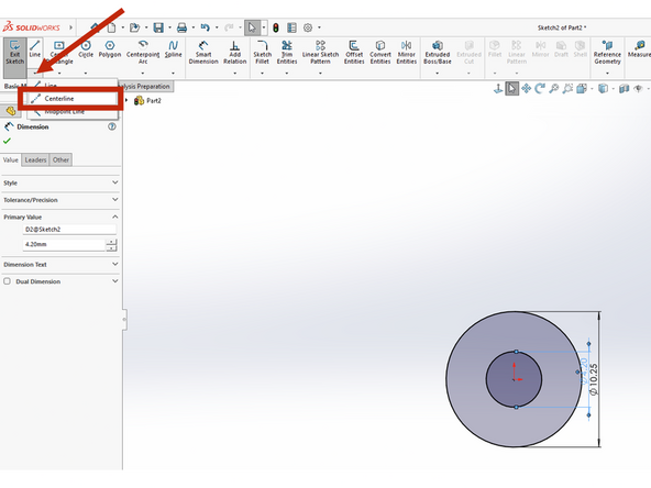
Zoom out and choose to create a Centerline.
-
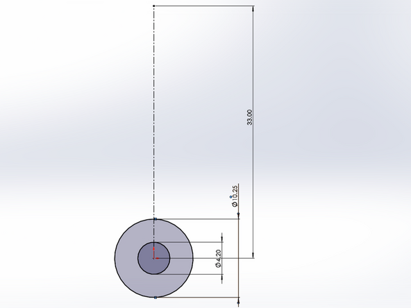
Click once to anchor the centerline in the center of your concentric circles. Now move the mouse up to create a dotted line extended up from your circles. Make sure the line is perpendicular by confirming there is a small yellow icon beside the line. Click one more time to end the line. The length of the line is not important.
-
Use the Smart Dimension tool to give the centerline a length of 33.
-
-
-
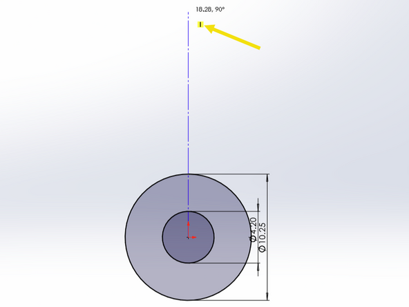
Create another circle and anchor the center of it at the top of the 33 mm centerline you just created.
-
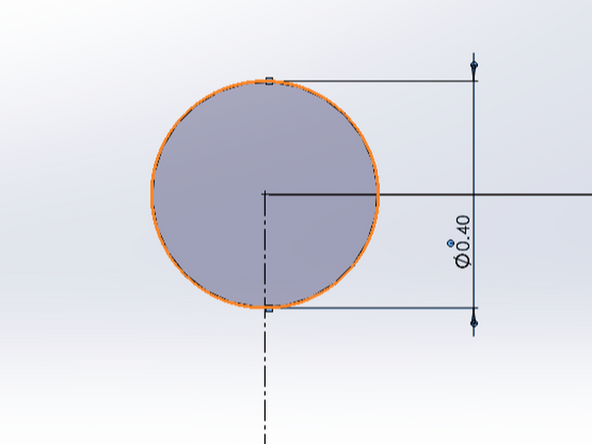
Use the Smart Dimension tool to give the circle a diameter of 0.4.
-
Note that this is a small circle relative to the others you created previously. You may need to zoom in to see a view similar to that shown here.
-
-
-
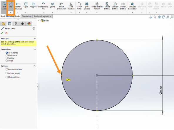
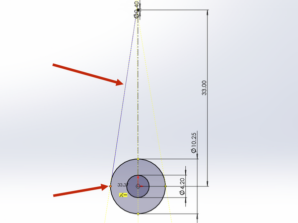
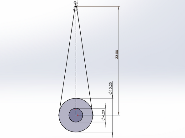
Within the Basic Modeling Tools tab choose to create a Line. Use your mouse scroll wheel to zoom in on the small circle if you have not already done so. Hover over the left edge of the small circle. An orange anchor point should appear. Click this point to anchor the line to be tangent to the left side of the circle.
-
Now zoom out and then zoom back in on the larger circle at the bottom of the screen. Hover near the left edge of the this circle. Click the orange anchor point on this circle to terminate the line at the tangent point on the circle's edge. Hit the escape key to stop drawing this line.
-
Repeat the same process to create an identical line on the right side.
-
-
-
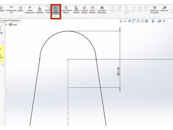
Click the Trim Entities button within the Basic Modeling Tools tab. Use the mouse scroll wheel to zoom in on the small circle.
-
Click below the bottom edge of the small circle and hold down the mouse button. Drag the mouse across the bottom of the small circle. The bottom arc of the circle will be trimmed up to the point where it intersects on either side with the tangent lines drawn previously. Release the mouse button. This will trim one quarter of the circle.
-
Repeat this trim procedure to remove the other bottom quarter of the circle. When you're done your sketch should look like the first image shown here.
-
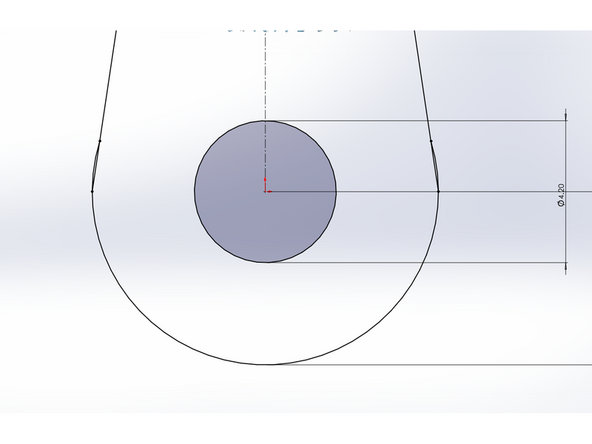
Now zoom out and then zoom in again on the bottom circle. This time click above the top edge of the bottom circle and drag the mouse across the circle top edge. The top arc should be deleted up to the point where the tangent lines intersect with it. Release the mouse button. Your sketch should now look like the second image here.
-
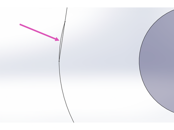
Finally, zoom in on one side of the large circle you just trimmed. The tangent line has created a cord as it intersects with the circle at two points. Click outside of the large circle and drag the pointer across this outer arc to remove it. Be careful to stop after crossing the arc and do not continue to trim the cord itself.
-
Repeat this trim on the right side of the large circle as well. An example of the final result is shown in the next step.
-
Be sure to hit Escape when you're done to exit the Trim tool.
It’s definitely worth zooming in pretty far when trimming, even to the point where it seems ridiculous. This ensures that you don’t trim more away than you want, which could cause problems in the next steps.
Matt Nowell - Resolved on Release Reply
-
-
-
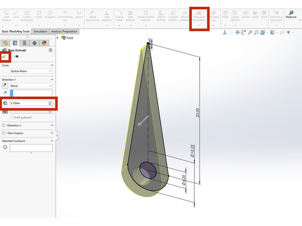
If you do not have a closed path for the pointer arm at this point, stop and return to the previous step. The extrude will only work properly if you have a closed path. A complete path should appear as a solid black outline with a grey shaded interior. You will also have a slightly darker grey circle at the bottom as shown in the first image here.
-
If your extrude in this step does not seem to be working check that you definitely removed the two small arcs from the previous step and left the two cords intact.
-
At the right side of the Basic Modeling Tools tab choose the Extruded Boss/Base.
-
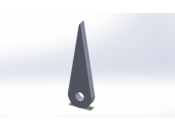
Enter a value of 3.1 mm for the height of the extrude and click the green check mark to complete the extrude.
-
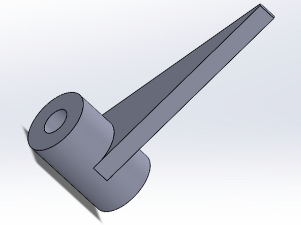
When you're done the part should look similar to the last example shown here.
Make sure the cords are attached to the actual base and not to another circle made on top of the base, otherwise, even if the correct sections are cut out, the closed path will not fill in.
Jake vanderheijden - Resolved on Release Reply
-
-
-
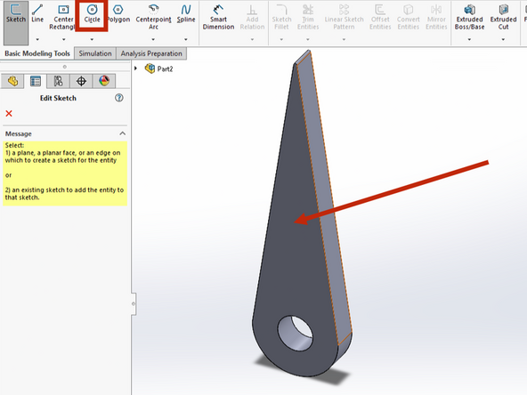
Create a new Circle. Since you completed the previous sketch+extrusion SolidWorks will ask you to select a planar face for your new sketch (circle). Click the broad face of your arm to select this face to use for your new sketch.
-
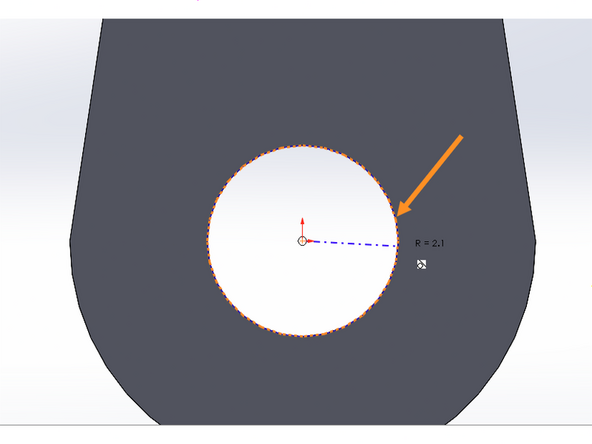
Anchor your circle in the center of the existing circle then move your mouse out from the center. If you hover near the edge of the existing center circle SolidWorks should snap to this circle and show you a dotted orange preview circle. Click your mouse to create this circle. It should match the radius of the existing circle, 2.1 mm.
-
Repeat this step to create a second circle, concentric with the first, and this time with a radius equal to the radius of the larger pre-existing circle, 5.13 mm. You can use the same trick of hovering over the edge of the existing larger circle and then clicking on it when it turns orange.
-
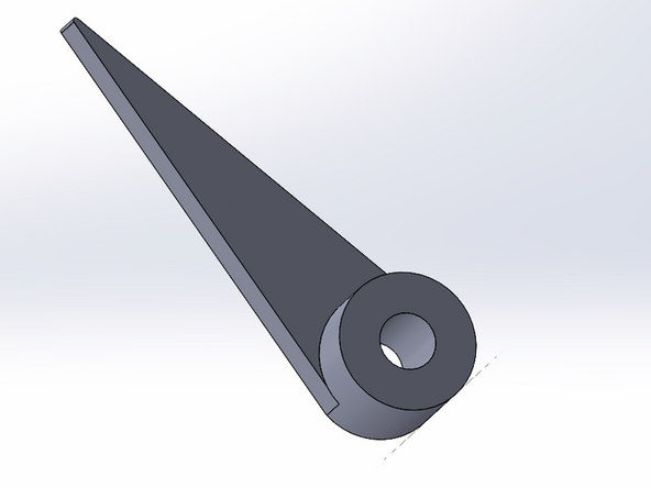
Extrude these two circles to a height of 5 mm. When you're done the arm should look like the final image here.
To see the ribbed preview make sure to click the '“full preview” option.
Asta Rustad - Resolved on Release Reply
-
-
-
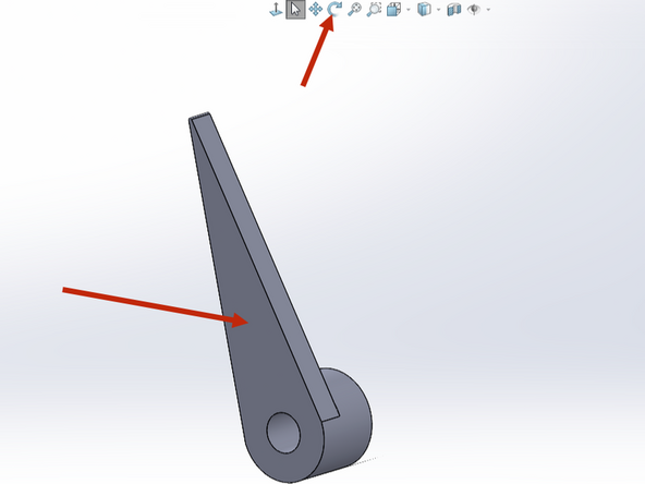
Use the Rotate tool to drag and rotate the arm so that you can view the flat, top face.
-
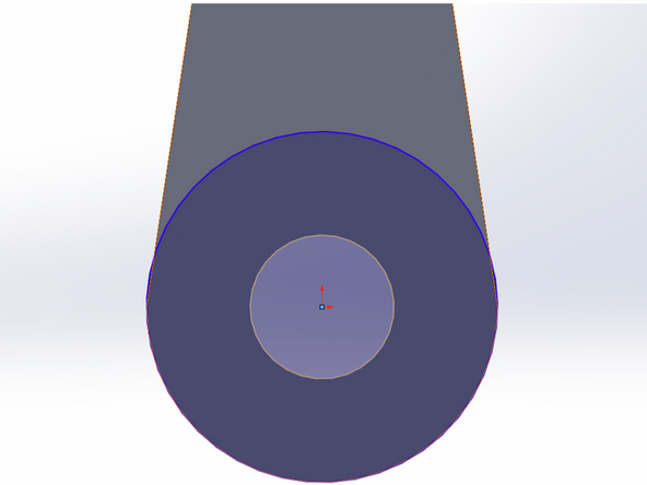
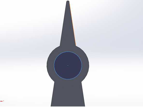
Use the Circle tool to create a circle that is concentric with the existing large circle at the base of the arm. Be sure to select the top arm face for your new sketch. Give this new circle a diameter equal to the diameter of the large existing circle.
-
Use the Circle tool to create a second concentric circle with diameter equal to the smaller existing circle (hole). When you're done your sketch should look like the second image shown here. Note the two concentric circles (blue outer, orange inner).
-
Finally, make an Extruded boss to extrude these circles away from the base. Choose an extrusion length of 6.9 mm.
-
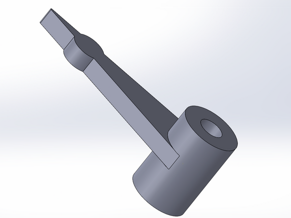
Rotate your arm when you're done so you can see both the top and bottom extrusions. Your arm should look like the third images shown here. Note that the top extrusion you just made is slightly larger than the bottom extrusion from the previous step (6.9 mm > 5 mm).
-
-
-
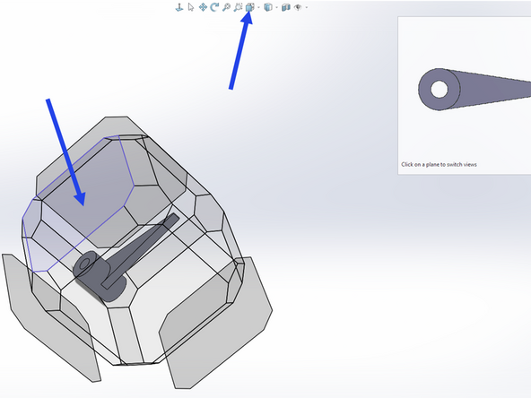
Use the View Orientation button and look at the arm from the top side. To do this you can click on the appropriate face of the superimposed cube that encloses your model. In the first image here the appropriate cube face is highlighted in blue. Clicking on this face will rotate your arm so you are viewing the top face.
-
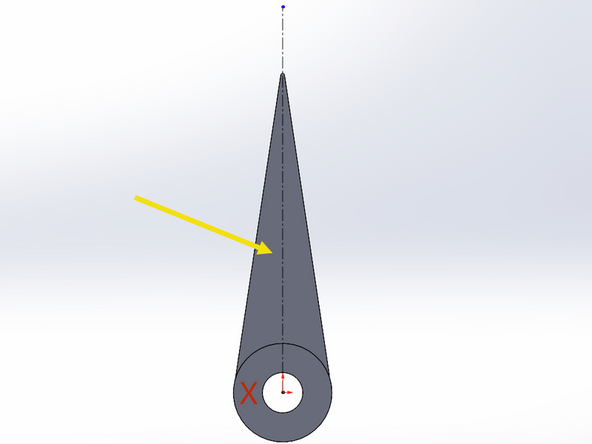
Draw a Centerline that is anchored at the origin & extends up beyond the tip of the arm. This line should be drawn on the face of the arm (yellow arrow) and not on the face of the extrusion (red X). Make sure the line is orthogonal with the axes like you did with your previous center line! Look for the yellow indicator symbol like last time.
-
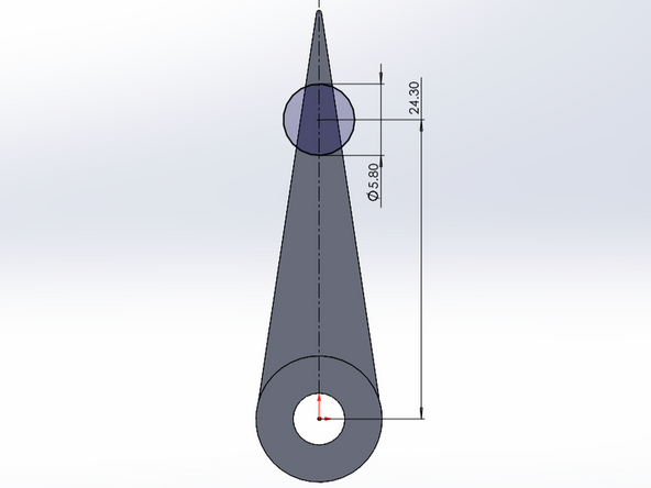
Draw a Circle that is centered on this new centerline. Place it at an arbitrary distance from the circular hole.
-
Finally, use the Smart Dimension tool to set the diameter of the circle to 5.8 mm. Also use this tool to define the center to center distance between your new circle and the existing circular hole. Set this distance to 24.3 mm. See the third image here.
-
-
-
Use the Rotate view tool so that you can see the new circle sketch from a side angle.
-
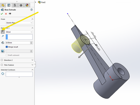
Choose to make an Extruded boss of length X. You may need to change the direction of the boss by clicking the Reverse direction button. Ensure that your extrusion points down and not up. SolidWorks will give you a preview of the extrusion in yellow. Make sure your extrusion looks like the first example shown here.
-
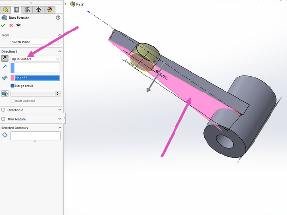
Sometimes it is helpful to define a face where your extrusion should end rather than an explicit extrusion length as we have done in previous steps.
-
Select Up To Surface from the Direction 1 dropdown menu. Rotate your arm again so that you can see the bottom face of the arm. Click on this bottom arm face and it should highlight pink. Confirm your view looks like the second image shown here.
-
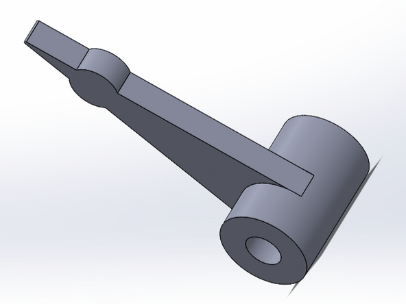
Click the green check mark when you're done to complete the extrusion. Your arm should look like the third image here.
-
-
-
Use the View orientation button to view the bottom face of the arm (highlighted in blue in the first image). Remember that the bottom side is the side with the slightly shorter circular extrusion.
-
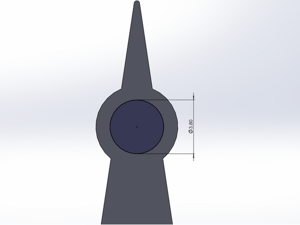
Create a Circle (make sure you choose the face of the arm and not the face of the circular shaft extrusion) and make it concentric with the magnet extrusion you made previously. Use the Smart Dimension tool to set the diameter of this new circle to 3.8 mm.
-
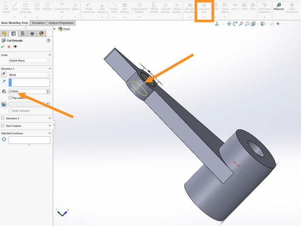
Choose to make an Extruded Cut. Rotate your view to confirm the direction is correct. Set the cut depth to 2.5 mm. See the final example image here.
-
-
-
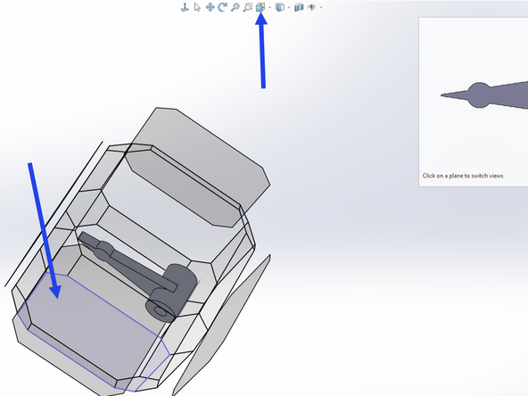
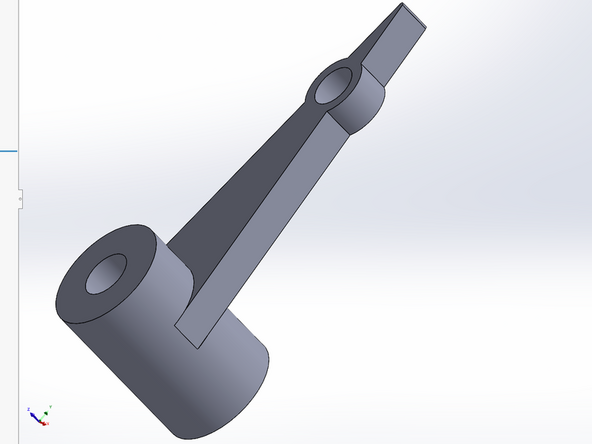
The cavity to hold your magnet should look like the image shown here. Make sure the cavity is on the bottom side of the arm! This is the side with the shorter circular shaft extrusion.
-
-
-
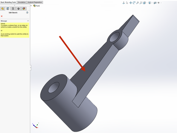
We need to have the printer cover the magnet. Create another Circle. Click on the bottom face of the arm (first image) when prompted to select a face for your sketch.
-
Anchor the circle in the center of the previous cut and click on the edge of the circular cut you just made (second image).
-
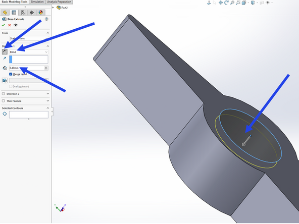
Make an extrusion of depth 0.4 mm. You'll need to return to making a Blind extrusion from the dropdown menu. Make sure you click the direction button to specify the correct direction. You want your extrusion to point down into the cavity in order to cover the magnet. See the final example image.
-
Click the green check mark when you're done to complete the extrusion.
-
-
-
Confirm the cavity at the end of your motor arm is now completely covered as is shown in this example image.
-
-
-
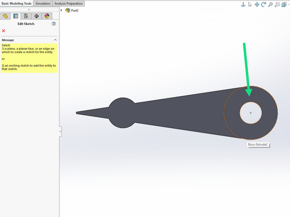
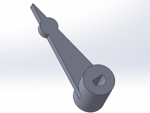
The shaft of our stepper motor is not perfectly circular but instead has a small slice taken out of it to make it asymmetric. This helps secure items to the shaft (like our motor arm) and prevent them from rotating. We need to create this D profile on our motor arm.
-
Use the View Orientation button to view the motor arm from the top or the bottom. Either view is fine.
-
Create a new Circle and choose the face of either the top shaft extrusion or the bottom shaft extrusion as your sketch face. Again, either orientation is fine.
-
Anchor the circle in the center of the existing shaft extrusion. Make the circle have the same diameter of the existing circular hole.
-
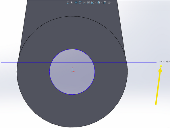
Create a Line and begin it outside of the left edge of the shaft extension. Extend the line to the right to the opposite right side of the shaft extension. Make sure the line is orthogonal to your axes! Look for the yellow indicator symbol. See the second example image. The length of the line does not matter.
-
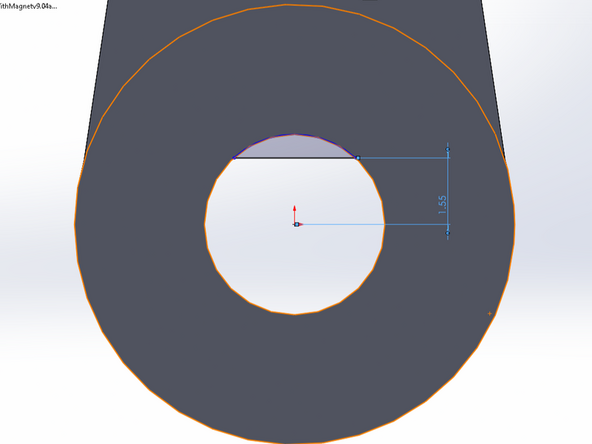
Use Smart Dimension to set the distance from the circle center to the line as 1.55 mm.
-
Use the Trim tool like you did previously to trim the left and right sections of the line that extend outside of the circle you created. Also trim the bottom arc of the circle. You should be left with a D shape, enclosed in blue. See the third example image.
-
-
-
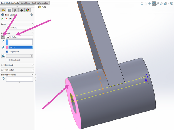
Create an Extruded Boss and rotate your view so that you can see the opposite side of the arm. Use the direction button again to ensure your boss is pointing the correct direction. Choose Up To Surface from the dropdown menu and then select the face of the opposite shaft extrusion which should highlight pink. See first example image.
-
Click the green check mark to complete the extrusion. Your arm should look like the second example image.
-
-
-
We need to place a cap on the top of our arm to limit how far the motor shaft can extend and set our arm at the proper height from the face of the DAMNED case.
-
Choose View Orientation and select the top side of your motor arm. Recall that the top side is the side with the longer shaft extrusion.
-
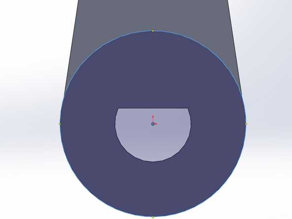
Create a Circle and select the face of the top shaft extrusion. Anchor the circle in the center of the D profile and set the diameter of the circle to be equal to the outer diameter of the shaft extrusion. See the first example image.
-
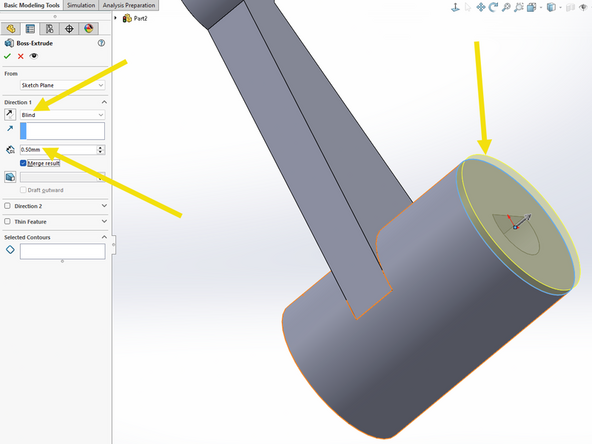
Return to a Blind extrusion from the dropdown menu. Confirm the direction points away from the motor arm and set the length of the extrusion to 0.5 mm. See the second example image.
-
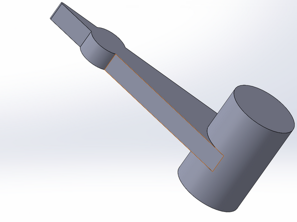
Click the green check mark to complete the extrusion. The top side of your motor arm shaft should now be completely covered as in the third example image.
-
-
-
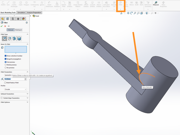
Our motor arm is thin and thin parts are often weak. In order to make the arm more robust we can create a fillet at the transition where it meets the shaft.
-
Click the fillet button. Hover over the circular line where the arm meets the shaft on the top side. This arc should illuminate orange. See the first example image.
-
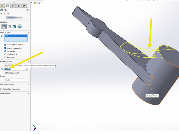
Set a fillet radius of 10 mm. You should see a preview in yellow.
-
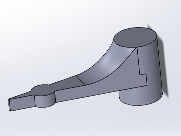
Click the green check mark to complete the fillet. Your arm should now look like the final image here, with a fillet on the top side of the arm.
-
-
-
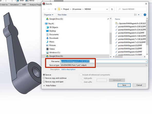
Save your part as a .sldprt file so that you can modify it later if necessary. You'll also need to submit this file for DA7.
-
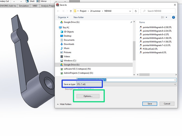
Also save your part as a .STL file. You will need the .STL file to 3D print. Note that you cannot modify an .STL file.
-
Be sure to click the Options button before saving the .STL file.
-
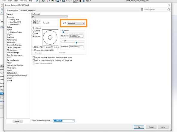
Becuase many 3D printer slicing applications operate in metric units, you should confirm that the Unit parameter of your STL file is set to Millimeters.
-
Click OK and then save your .STL file.
-
SolidWorks will pop up a window telling you how many triangles your part contains. Click Yes to continue saving.
Thanks for the reminder, Henry! I modified this step to indicate that. It should save folks time and confusion.
Matt P. Lamparter - Resolved on Release Reply
-


Congratulations! You now know enough SolidWorks to be dangerous. YouTube and the builtin SolidWorks tutorials are your friends. SolidWorks is a powerful, full featured tool. Anything you want to accomplish has already been done. Use an internet search to find a video detailing the steps necessary to accomplish anything more complex than what is provided in this tutorial.
Congratulations! You now know enough SolidWorks to be dangerous. YouTube and the builtin SolidWorks tutorials are your friends. SolidWorks is a powerful, full featured tool. Anything you want to accomplish has already been done. Use an internet search to find a video detailing the steps necessary to accomplish anything more complex than what is provided in this tutorial.
Cancel: I did not complete this guide.
15 other people completed this guide.
Team
18 Comments
If you’re trying to customize the piece and can’t seem to get it to extrude, try going back to your sketch and trimming the little lines that are leftover. You also may have not created an enclosed shape. The shape has to be enclosed for the software to successfully extrude it.
Hunter Guthrie - Resolved on Release Reply
To write on the top of the arm, make sure the top plane is selected and create a general shape there. Next, select the shape and you can add text to that area. For the arm, I would recommend using an extrusion greater than 1.5 mm to be able to see clearly the small text.
Abby Bayuk - Resolved on Release Reply
To write on the top of the arm, make sure the top plane is selected and create a general shape there. Next, select the shape and you can add text to that area. For the arm, I would recommend using a extrusion greater than 1.5 mm to be able to see clearly the small text.
Abby Bayuk - Resolved on Release Reply
This was definitely a good introduction to Solidworks, and I feel it taught us the necessary amount to make things on our own.
Chris Toomey - Resolved on Release Reply
Great guide, good introduction to solidworks basics and CAD modelling
Izzy Philosophe - Resolved on Release Reply
When I first opened SolidWorks, I was overwhelmed with the menus, options, and all the things. This tutorial was clear, concise, and instantly rid me of my anxieties about using it.
Benjamin Buentello - Resolved on Release Reply
This guide is very user-friendly, as long as the user reads carefully what each bullet point is saying, as well as looks at a visual example with the provided images, any user can definitely design such piece. I had no previous experience with SolidWorks, but this guide made everything seem so easy. Unfortunately, I can’t 3D print from home, but my design looks exactly like the one on the examples, so I am confident that if I were to 3D print it, it would print correctly.
Pedro Carneiro Passos - Resolved on Release Reply
I felt that this guide was comprehensible, and would definitely recommend having the guide and Solidworks visible at the same time, as going back and forth between windows was not ideal.
Wolfgang VonGetzie - Resolved on Release Reply
Something that helped me was when extruding/cutting/adding a fillet, the tab on the left part of the screen will tell you what you have selected so far. This helped me during the fillet step to make sure that I had selected all 4 edges and did not select the face before completing the fillet.
Sivanne Bachrach - Resolved on Release Reply
A very helpful guide, it walks me through each step and I could go back and look at the images to confirm my arm looks correct. I would suggest not skipping through any instructions because it will be frustrating to go back once you think you’re finished.
Alvin Huynh - Resolved on Release Reply
This was an informative guide although I did have to do a little bit of figuring things out on my own so it was a perfect opportunity to learn some of the software package.
Tyler Burns - Resolved on Release Reply
This was a great way to learn solid works and it ended up printing perfectly.
Darren Miller - Resolved on Release Reply
leaving a comment, I’ve worked a good bit with solid works so I feel decent with it, although I probably wont be using it for this since the laser cutter arm just seems easier
James Howe - Resolved on Release Reply
leaving a comment, I’ve worked a good bit with solid works so I feel decent with it
James Howe - Resolved on Release Reply
Solidworks is a very important tool for me to use for future assignments and do 3D designing. I think having familiarity with these apps will help me a lot in the future as an engineer.
Zihao - Resolved on Release Reply
Solidworks is a very versatile program which takes a lot of getting used too but once you get a hang of the program you can easily become proficient with it. My biggest struggle when using solidworks is having everything be defined.
Lucas Sklavos - Resolved on Release Reply
The version I downloaded looked a little different. But if there are anything you can’t find in the this tutorial, Youtube will be helpful.
Ben Ma - Resolved on Release Reply
Downloading this to your own device requires a great deal of storage, so ensure you have a sufficient amount of storage before beginning the download process, which does take a bit of time
Taylor LaMantia - Resolved on Release Reply
This entire tutorial is also possible using a competing software of Solidworks, called Autodesk Inventor. Many of the tools have similar names and layouts. While the two programs use different file types for their working 3D models, both have implemented features to import files from either one.
Cole Zehe - Resolved on Release Reply