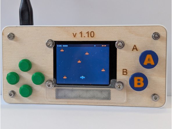
Introduction
This guide will walk you through the steps of assembling a DAMNED device. You will be provided with the BOM (bill of materials) and the guide will explain each step of assembly. This guide assumes you have completed all prior steps of 3D printing and laser cutting parts and soldering components to the PCB.
-
-
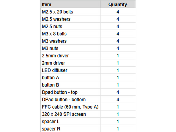
Confirm you have everything on the bill of materials (BOM).
-
In addition to these parts you will need the items you assembled during the previous Design Assignments:
-
Populated PCB
-
3D printed enclosure base
-
Laser cut top panel
-
-
-
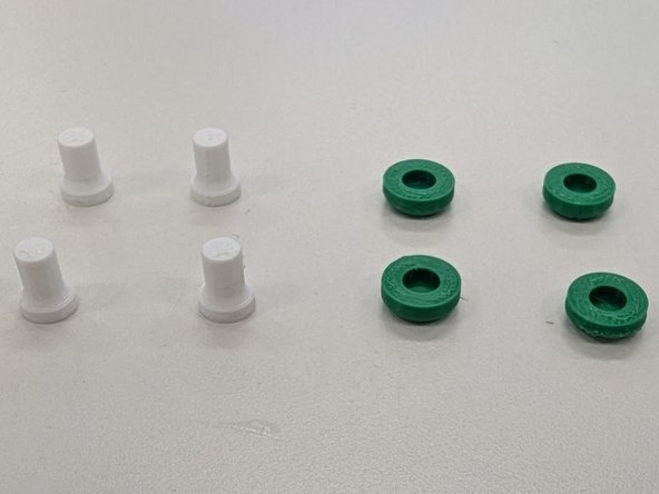
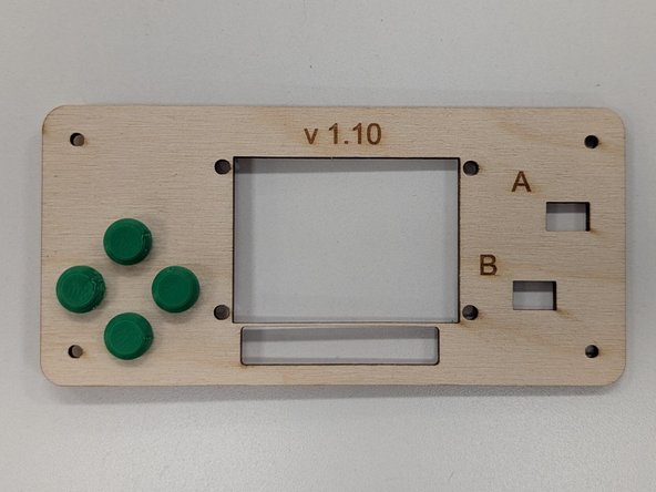
Locate the four button tops and four button bottoms.
-
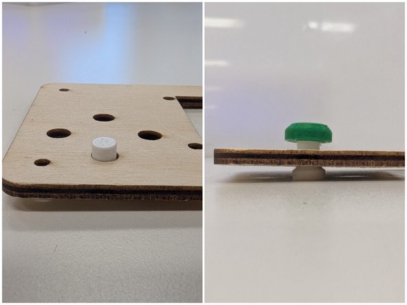
Insert a single button bottom from the back side of the top panel so that it protrudes from the top.
-
Place a button top on top of the protruding post of the button bottom. Make sure the two are in straight alignment.
-
Using consistent, even force from top and bottom, press the two button pieces together. You should feel the post of the button bottom lock into the button top.
-
Repeat this process for all four of the button assemblies.
-
-
-
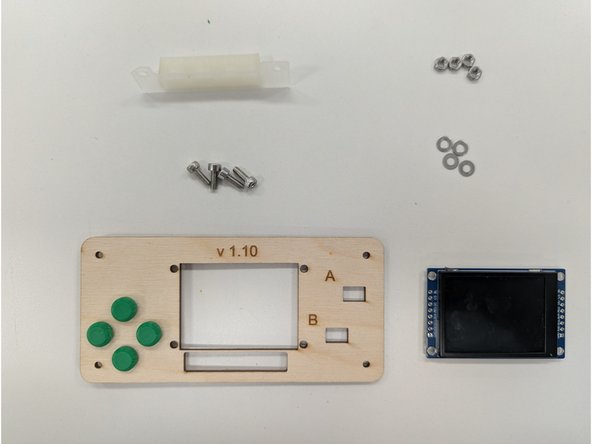
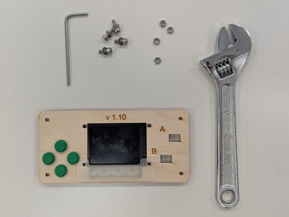
Locate the following:
-
M3x8 bolts, M3 washers, M3 nuts (quantity 4 each)
-
LCD screen
-
opaque plastic diffuser
-
your laser cut top panel
-
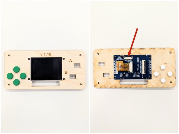
Remove the LCD from its plastic case. Insert the screen in the large rectangular slot in the laser cut top panel from the back side of the top panel. The screen bezel should fit snuggly in the slot. Be sure that the FFC connector on the back of the screen faces the top of the panel. See image here.
-
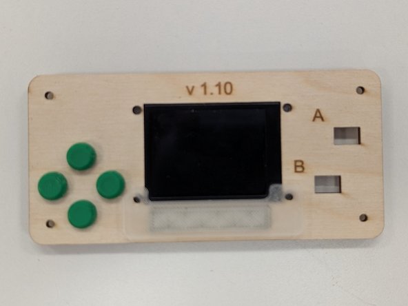
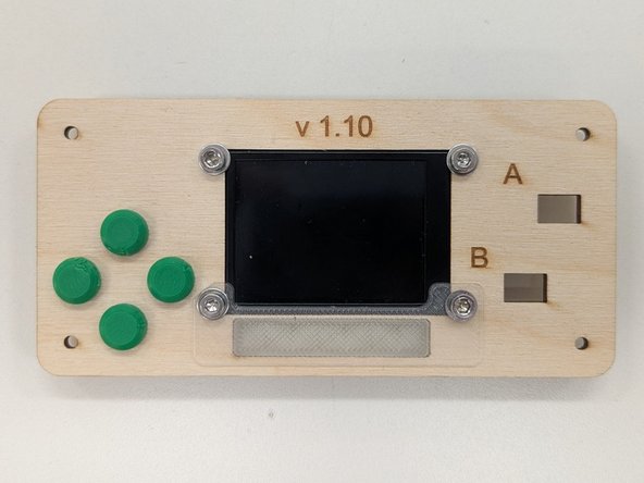
Insert the opaque plastic diffuser in the smaller rectangular slot in the top panel as shown in the image. Insert it from the front of the panel so that it fits flush with the panel and the flange holds it in place. See final image here.
-
-
-
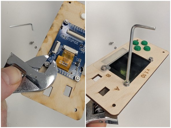
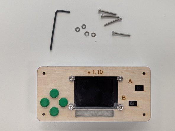
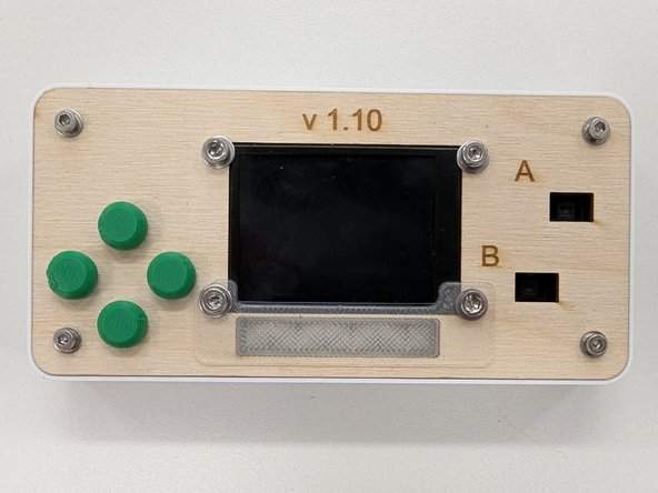
Slide washers onto the four M3x8 bolts. Insert the bolts+washers into the four screen mounting holes from the front side of the laser cut panel.
-
Locate the provided 2.5 mm hex driver. Also locate a small adjustable wrench from the Maker-E or Mooney.
-
Use the adjustable wrench to hold a nut stationary from the back while you use the hex driver to tighten the bolt from the front.
-
Snug each of the four bolts so that the screen is secure.
-
RETURN THE ADJUSTABLE WRENCH WHEN YOU'RE DONE! LEAVING TOOLS OUT IS INCONSIDERATE OF OTHER MAKERS OF A MAKERSPACE.
-
-
-
The screen attaches to the PCB via a compact cable called a flat flex cable or FFC.
-
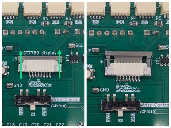
The FFC connectors on both the screen and PCB need to be opened in order to accept the FFC. They both open via slightly different methods.
-
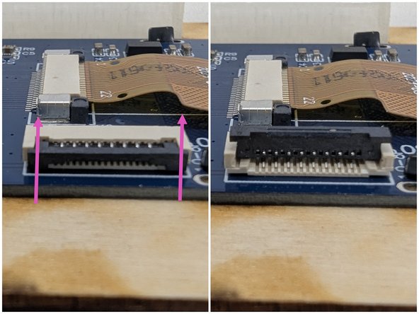
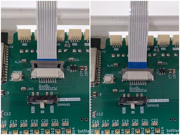
Locate the FFC connector on the PCB. Gently push the grey part forward, away from the white plastic housing until it stops.
-
Locate the smaller of the two FFC connectors on the screen. Gently flip the black plastic up so that it is perpendicular to the white plastic housing.
-
FFC connectors have a limited number of open/close cycles before they wear out. They are not designed for repeated open/close cycles. It is OK to repeat this cycle a small handful of times to ensure the cable is seated properly (next step) but refrain from unnecessarily opening and closing these connectors.
-
-
-
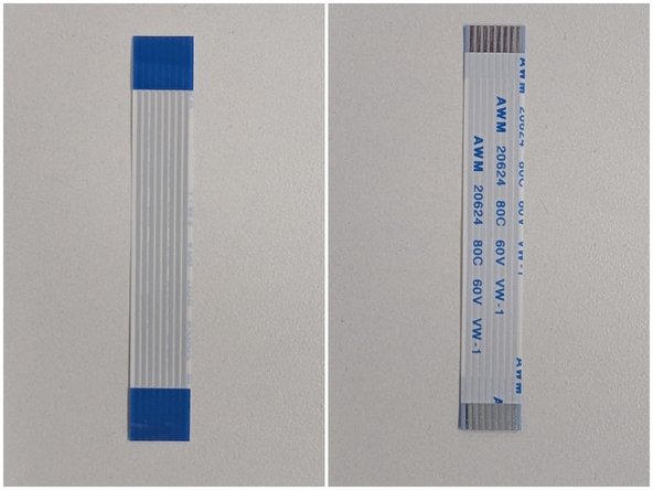
Locate the 60 mm Type A FFC cable. Type A refers to the fact that both ends of the cable have exposed leads on the same side. Notice that if you flip the cable over the reverse side has blue plastic reinforcement (insulating) tabs.
-
A Type B cable would have exposed leads on opposite sides of the cable.
-
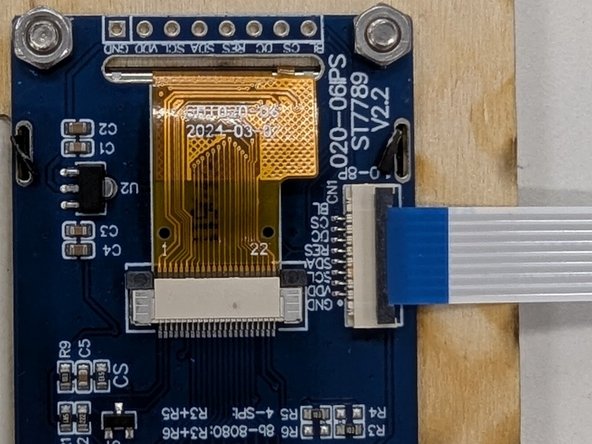
Insert one end of the FFC cable into the open connector on the screen. Make sure that the shiny exposed leads are pointing down, away from you. The blue plastic reinforcement tab should be facing up.
-
With the cable fully inserted into the connector push the black plastic clasp down to lock the cable in place. Give the cable a gentle tug to make sure it is held in place and does not detach from the connector.
-
-
-
During the 3D printing process it is likely that a little bit of lose filament was laid on top of the opening of the embedded hex nuts. This excess, unwanted filament will cause problems when you go to thread the long M2.5x20 bolts into these nuts. You need to clean out these mounting holes first.
-
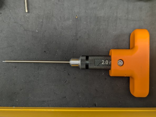
Locate the straight-handled 2.0 mm hex driver with an orange 3D printed handle extension. This tool is found in the yellow DeWalt tool cabinet in the back of the Maker-E. Check the drawer labelled, "SCREWDRIVERS, TORX + SECURITY BITS".
-
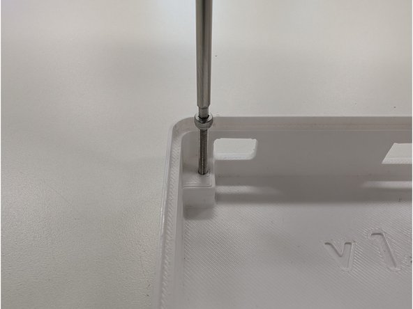
Insert one of the M2.5x20 bolts into a hole in your enclosure. Place the enclosure on a flat surface. Use the 2.0 mm hex driver to screw in the bolt and be sure to apply significant downward pressure. Go slowly until you feel the bolt grab the threads of the nut.
-
With a little bit of practice you should be able to thread this same bolt into all four of the holes in the enclosure properly. Thread it down all the way until it stops. Do not over-tighten these bolts as this can damage the 3D printed enclosure and cause the nuts to rotate, rendering them less useful.
-
Be sure to return this special 2.0 mm hex driver when you're done so others can find and use it!
-
-
-
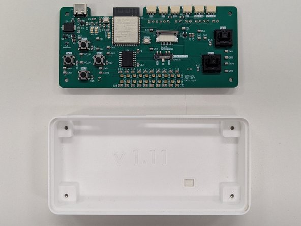
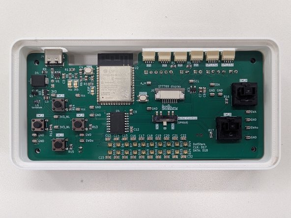
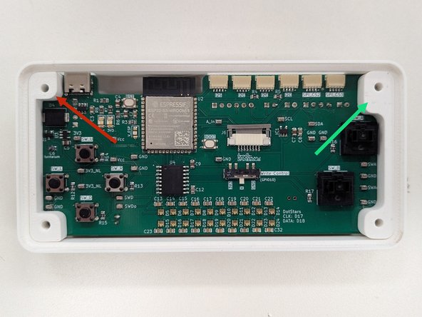
Place the PCB in the 3D printed enclosure so that the USB C connector lines up with the small rectangular opening in the enclosure. The row of STEMMA QT connectors should align with the larger opening.
-
It may be necessary to slightly tilt the PCB forward or backwards in order for it to rest securely in the enclosure. Do not force the PCB! If you encounter resistance stop and re-align the PCB, then try again.
-
Place your 3D printed spacers on either side of the PCB. These will provide support for the faceplate and provide guides for the 2.5x20 mm bolts to thread into the embedded hex nuts in the bottom of the enclosure.
-
The left spacer is the slightly smaller of the two spacers.
-
The right spacer is the slightly larger of the two spacers. The wider extrusion should be located towards the top edge of the PCB.
-
-
-
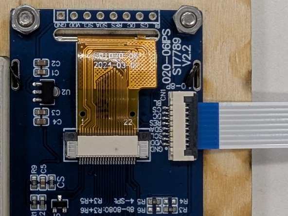
Take the remaining end of the FFC cable and insert it into the FFC connector on the PCB. Again, make sure that the blue reinforcement side is facing up towards you.
-
Slide the cable as far back as it will go in the connector. This can be slightly difficut because of the angle here. Persevere!
-
Once the cable it fully inserted, push the black latch down to clamp the cable in place. Give the cable a gentle tug to confirm it is securely held in place. If it comes out you'll need to open the connector and try again.
-
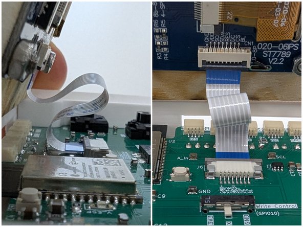
Gently fold the FFC cable back on itself as shown in the images here. Do not make sharp bends or creases in the cable as this can damage the conductors.
-
With the cable properly folded back and entirely within the enclosure and underneath the faceplace, press the faceplate down into the recessed slot in the enclsoure. It should sit nearly flush with the edges of the enclosure.
-
Maker sure to fully press the faceplate into the recessed area so it sits flush with the printed edges. This is important to ensure that the buttons can press properly.
-
-
-
Locate the four M2.5x20 mm bolts as well as the four M2.5 washers and the 2 mm hex driver.
-
Place a washer on each bolt.
-
Thread one bolt through each of the four holes in the corners of the face plate.
-
Tighten the bolts just until they are snug. Do not over tighten the bolts or you could loosen the embedded hex nuts in the 3D printed enclosure.
-
-
-
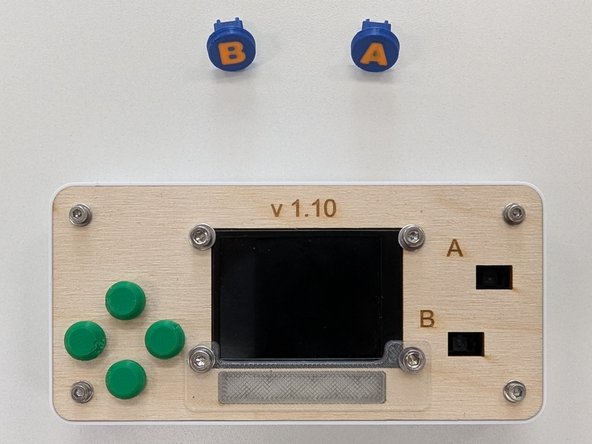
Within your kit of parts, locate the remaining two 3D printed button caps labelled A and B.
-
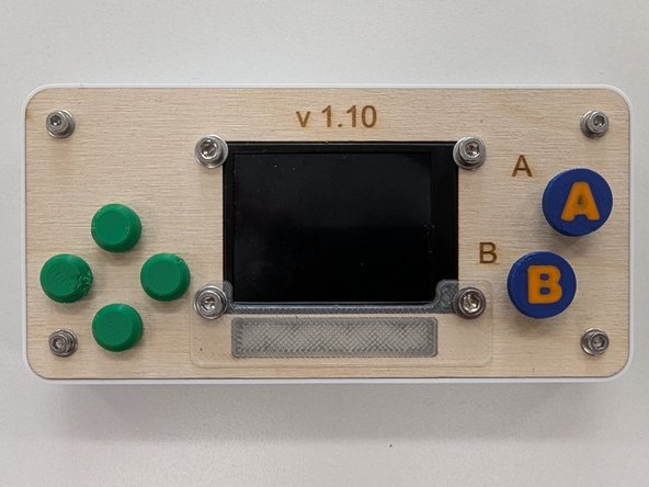
Carefully insert the A button cap into the top right button slot of the faceplate. Use caution as there are very small tabs on the print that need to be lined up with slots in the button itself. Go slowly and use gentle pressure at first until you feel the tabs insert into the slots of the button.
-
Once you are confident that the button cap is lined up properly, press firmly down on it until it will not press any farther. The button cap should not touch the wooden faceplate when pressed down fully.
-
Repeat this process with the B button cap and the remaining button slot on the faceplate.
-
-
-
Turn the volume up on your device so you can hear the button clicks in the example video.
-
Check all six buttons to confirm they actuate the buttons properly.
-
The four left button caps should all have an audible "click" sound when they are pressed. The button press should feel crisp. The 3D printed button cap should not touch the wooden faceplate.
-
If any of the button presses feel "mushy", they do not audibly click, or the button cap touches the faceplate then you need to remove the faceplate and adjust the button cap assembly.
-
The two right button caps will not feel quite as "clicky" as the left buttons. However, they actuation of the button should feel consistent and springy. The button cap should return easily to the up position after being pressed.
-
If the button cap does not easily return to the up position, or it gets stuck at some point, you need to remove the button cap and try to reconnect it properly with the button on the PCB.
-
-
-
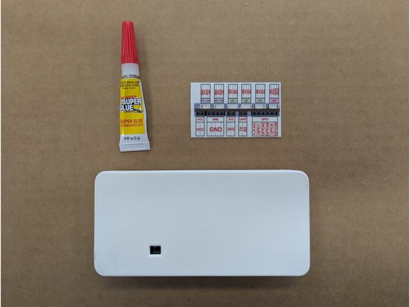
Work over a scrap piece of cardboard for this step so you do not get glue on the Maker-E benches or tables!
-
Find the laminated IO (input/output) label in your kit of parts.
-
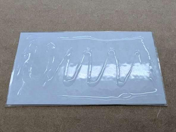
Apply a small layer of super glue on the back of the IO label. Be sure to get the glue up to the edge so the label does not peel off of your enclosure.
-
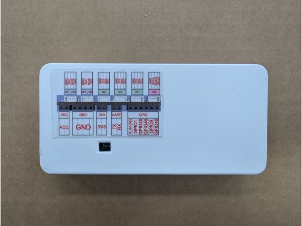
Carefully flip the IO label over and apply it with firm, even pressure to the back of the enclosure as shown in the figure here.
-
-
-
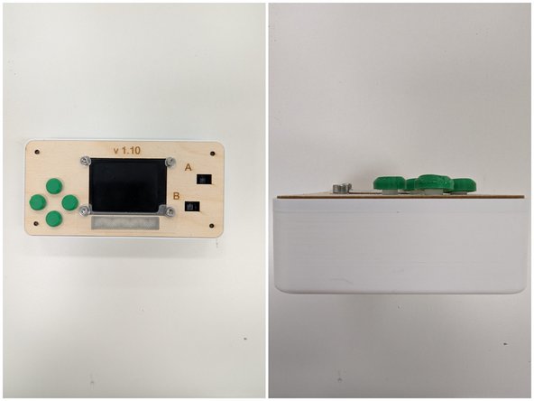
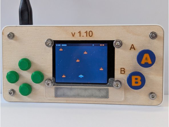
Congratulations! Your project is now fully assembled.
-
Time to start working on software.
-
Cancel: I did not complete this guide.
9 other people completed this guide.

Team

17 Comments
I had some trouble with connecting the 3D parts together at the end of the tutorial- maybe the sizes could be adjusted a little bit differently.
Elif Tuncel - Resolved on Release Reply
The hardest part is definitely soldering the one lead to the PCB right next to the IC. You really have to be careful.
Hunter Guthrie - Resolved on Release Reply
Great tutorial! Make sure to have all of the glued wood line up correctly for the case to fit!
Abby Bayuk - Resolved on Release Reply
Great tutorial, really went into a helpful amount of detail in each step.
Izzy Philosophe - Resolved on Release Reply
The instructions for mounting the PCB onto LED ring assembly in Step 7 could be just a bit more clear, maybe with *MAKE SURE YOU . . .* or something that lets you know that the spacers go around the bolts and not the soldered wires. I made that mistake, and after the wires have been bent a bit, they fit through the holes very tightly, and when I mistakenly thought I had to take the PCB off because I thought I forgot the spacers, I thought that I was going to pull them out. A small note at the beginning of the section would be great
Benjamin Buentello - Resolved on Release Reply
This guide was a great tutorial. I only had trouble soldering the wires onto the PCB because of how close the wire was to other components, but otherwise everything was very straightforward.
Wolfgang VonGetzie - Resolved on Release Reply
Very good tutorial, the only problem I had was trying to get the first screws to thread on the nuts. With the washer on there was not quite enough threads to get a good connection.
Chris Stankus - Resolved on Release Reply
This guide is very simple and does a good job laying out every step you need. However, do not get carried away with the simplicity because you could end up using the wrong screws! Something I did but fortunately I was able to recover.
Alvin Huynh - Resolved on Release Reply
When assembling make sure that you have the colored wires coming out of the correct location. I did not check those wires and ended up having to take everything apart before putting it back together again. This is important to notice because the next step is to solder and if you solder before realizing your mistake, it will be a long, difficult process to undo your soldering. Additionally, it is important to not be scared to push a bit when assembling. The case had more give then I realized.
Sivanne Bachrach - Resolved on Release Reply
The design is definitely beautiful. My younger brother (who is very crafty) was actually right next to me as I was doing it and he asked me if he could try assembling some parts. I let him do steps 9 through 14, and he did a great job, so I just want to make sure I include his comments as well. He said: “It was very self-explanatory and easy to follow. The pictures help a lot. I wish I could take this class when I am at Bucknell.” From my part, I want to say that instructions were very clear and definitely anyone can complete the assembling part with no major problems.
Pedro Carneiro Passos - Resolved on Release Reply
Good design and tutorial, just wish the screws for mounting the acrylic diffuser piece were wood screws so that they could more easily bite into the wood and thread, since there isn’t a nut on the other side of them anyway. Would also be nice to include that you may have to put the ring + plywood into a vice to avoid it breaking the glue between the two laser cut pieces, since I had to apply glue again after that happened to me.
THanks, Ryan! I’ll probably supply wood screws the next time we run this course. Can you shoot me an email with a bit more details on that last bit? I’m not sure I follow.