
Introduction
UART is another form of communication between devices that, while outdated, can still be useful for many components. This guide will introduce you to UART concepts and show how they can be used with components. Learn more about the technical side of UART here.
Tools
Parts
-
-
Before you complete this tutorial, make sure that you have completed the Feather M4 Express tutorial first.
-
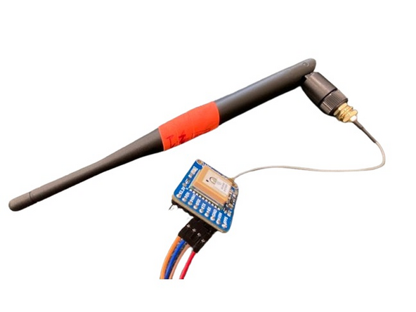
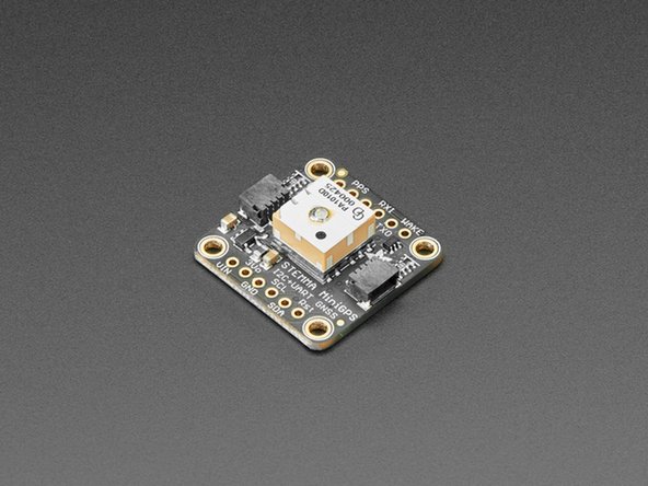
You will also need the Ultimate GPS Breakout V3 from Adafruit and 4 female-to-male jumper cables.
-
-
-
UART is a serial method of communication. This means that it is synchronous transmission between two devices, one singular bit at a time. There is no parallel communication. This makes it significantly slower than most modern protocols (based on the baud rate), but some boards still only use UART(due to its simplicity), so it's important to learn.
-
UART works by simply connecting a "transmit" pin to a "receive" pin, or TX and RX. Usually, these two are intertwined, each device having an RX and TX pin. Bridging these with jumper cables allows communication from each respective TX pin to the other device's RX pin. To learn more visit this link.
-
Start with the blue GPS breakout board. In this case, the Feather will be UART 1 and the breakout board will be UART 2. To connect this specific breakout board to the Feather, connect VIN to 3V on the Feather and GND to ground. Then take jumper cables on TX and RX and attach them to the opposite label on the Feather. That's it! All connected.
-
-
-
To use CircuitPython for this tutorial, you will need the adafruit_gps.mpy library from the common bundle.
-
Make sure the version matches your installed CircuitPython version.
-
-
-
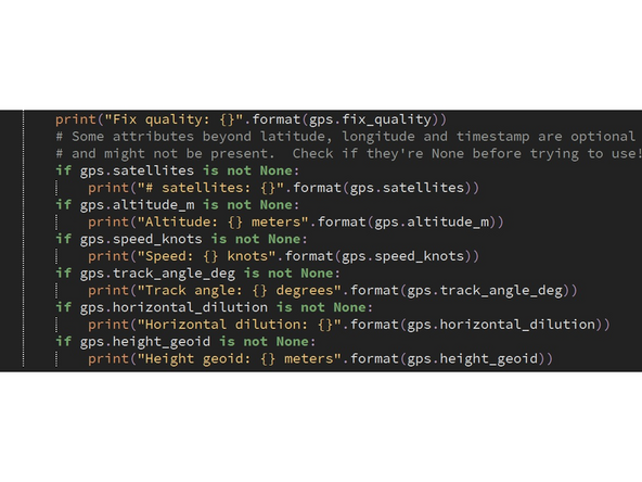
After defining the GPS object with UART or I2C, there are some common commands that are useful for the board. gps.update() updates the GPS status and re-requests any and all satellites it can reach for data. gps.satellites, gps.altitude_m, gps.speed_knots, gps.track_angle_deg are all relatively self-explanatory.
-
gps.has_fix is a boolean that will tell you if the GPS was able to be reached and has information to give. It's important to check for this because this board only has an integrated antenna, which means it is quite inconsistent in receiving data. Checking for this variable in a loop allows your code to keep running instead of simply erring.
-
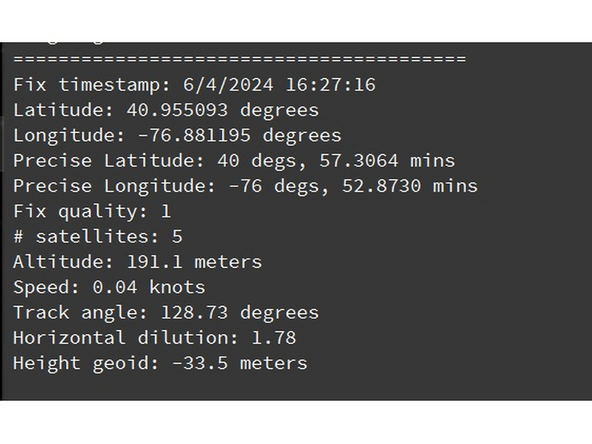
Use the Adafruit example code to make sure that your board is hooked up correctly. If you only receive Waiting for a fix..., you may need to move the antenna on the board. If having trouble, use the exterior antenna included in the kit to extend range. This may enable you to get a signal from indoors. If not, you may need to go out back to a clear area.
-
-
-
To earn a badge for UART and GPS, use the other GPS breakout in the kit to connect to UART. This board uses the same libraries (and maybe even same code). Use the Adafruit website to find its pinout and get it working with UART.
-


UART communication and GPS: Quiz