Introduction
This tutorial assumes you have completed the PCB Design Part 1: Multisim tutorial. We begin with a brand new Ultiboard file where all of your components have been imported from Multisim, along with the corresponding connections in the form of a ratsnest. You should change your board outline before placing any components or traces.
-
-
Define your board shape prior to placing any components. While it is still possible to change board shape after placing components and traces, it will make your life easier to do this step first.
-
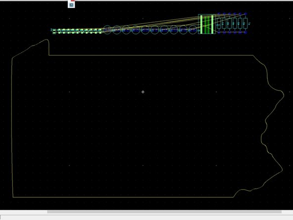
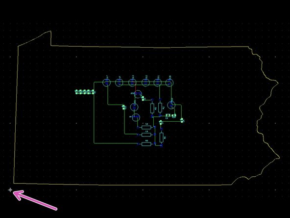
In the example shown here the components have been imported from Multisim but they have not yet been placed inside of the default board outline.
-
-
-
If you want something simple like a circle or a rectangle with rounded corners, Ultiboard has the ability to create these natively. Double click the Board Outline layer to activate it, then choose Place -> Graphics and choose the shape you desire.
-
With your shape type selected, arbitrarily draw a shape someplace on the screen that does not overlap with the default rectangle. Here we have chosen a circle.
-
Once you have your shape on the screen, be sure that the Enable selecting other objects button is toggled. Then right click on your shape border and choose Properties. This will allow you to specify dimensions for your board shape.
-
Finally, delete the original rectangular board shape be clicking on it and pressing the Delete key.
-
-
-
If you want a more customized shape than Ultiboard can create you will need to do one of two things:
-
Create your own shape from scratch using your design software of choice (SolidWorks, AutoCAD, Inkscape, Illustrator, etc.)
-
Find an existing design you like and use that.
-
It is the second option we will explore here. Both options need to converge on the same end result: a DXF file which can be imported into Ultiboard. More on that in a later step.
-
-
-
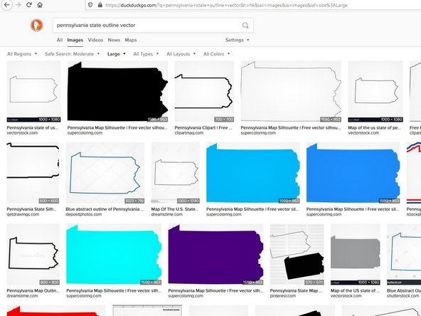
Begin with an online image search for whatever shape you are looking for. Include the words "outline" and "vector" for the best results.
-
Look for a high contrast (black and white) image if possible. Ideally it will be an outline, but filled shapes can work as well. Get the largest image you can find. Copy or save the image.
-
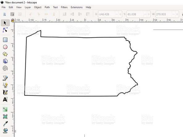
Launch Inkscape (available on all Maker-E computers). Paste or import your image into Inkscape.
-
-
-
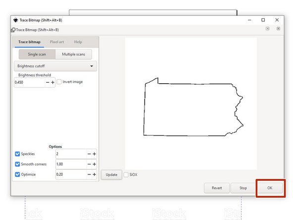
You now need to convert your bitmap (pixel) image into a vector (line) image. Inkscape has a tool which will accomplish this conversion. Follow their tutorial here.
-
We recommend using the "Brightness cutoff" or "Edge detection" methods outlined in the tutorial. You will need to experiment with the associated parameters until you end up with a result you like. Be sure to click OK in the dialog when you are done. You can then close the Trace Bitmap dialog window.
-
You now have two objects: your original bitmap image and your vector image overlaid on top of the bitmap. Click and drag the vector off to the side and delete the original bitmap.
-
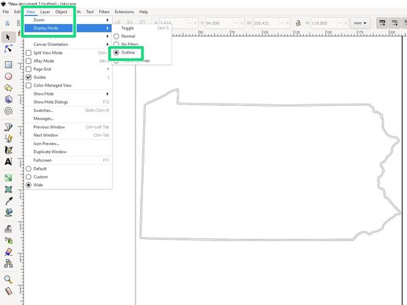
Delete the original bitmap. Then from the View menu, choose Display Mode -> Outline. You should see your shape, as an outline, possibly with two concentric outlines.
-
-
-
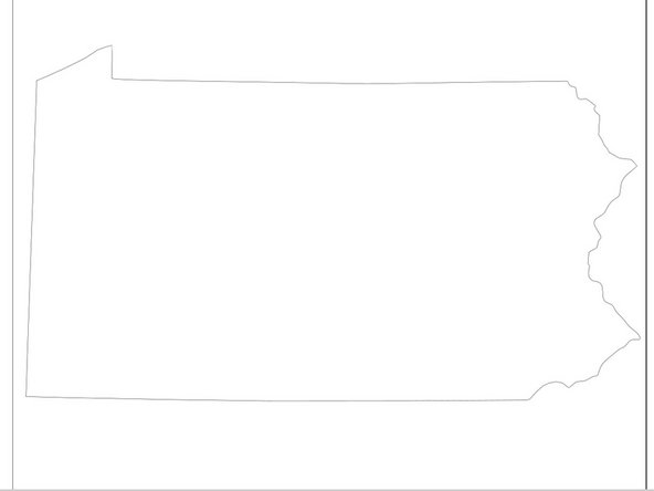
If you're lucky, you now have two continuous, closed loops in the shape of your outline, one inside of the other. See the example shown here.
-
If your result is different (there are small, discrete artifacts, the loops intersect or are not closed, etc.) you should ask the Lab Director or a Maker-E Assistant for help in cleaning up your outline.
-
Assuming your result looks similar to the example you need to delete one of the two outlines. Click on your image to select it, then choose Path -> Break Apart.
-
You should now have the ability to select the outlines independent of one another. Choose one outline and delete it.
-
-
-
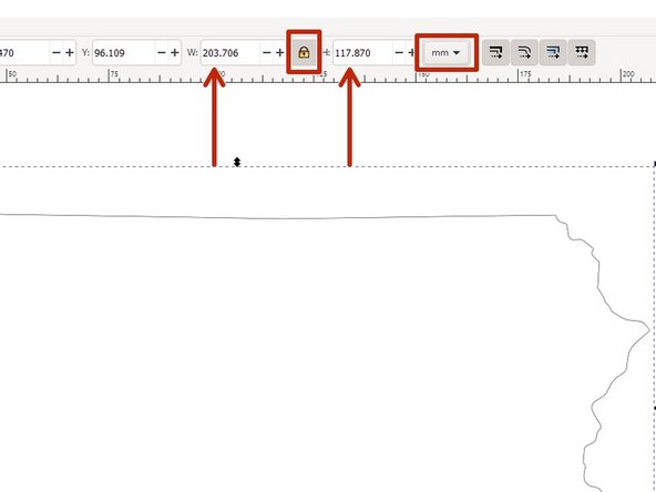
Now you need to scale or size your shape appropriately. Change the document metric to your desired format: mm or inch. Click on your image to select it, then be sure to click the lock icon to scale proportionally. Enter your desired height and/or width.
-
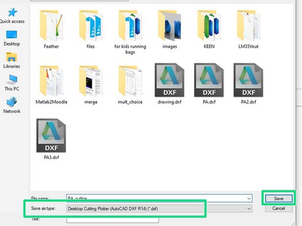
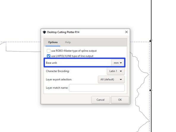
When you are happy with the result, choose File -> Save As. From the dialog window that appears, choose a Save as type of "Desktop Cutting Plotter (AutoCAD DXF R14) (*.dxf)".
-
Give your file a name and click Save.
-
In the dialog window that appears, confirm that the Base unit matches the metric you chose earlier. In this example both choices are mm.
-
-
-
Within Ultiboard choose File -> Import -> DXF. Locate the DXF file you just saved from Inkscape and import it into Ultiboard.
-
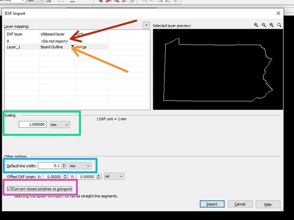
Within the DXF Import dialog window, make the following changes:
-
Set DXF Layer 0 to Ultiboard layer <Do not import>
-
Set DXF Layer Layer_1 to Board Outline (you should see your outline appear in yellow)
-
Set the scaling to 1.0 and the metric to match what you chose in Inkscape. In this example that is mm.
-
Set the Default line width to 0.1 mm
-
Check the box for Convert closed polylines to polygons
-
Click Import.
-
-
-
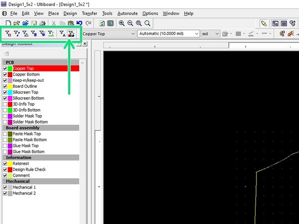
Your outline is now in Ultiboard, but it is represented as many small discrete lines. It is possible to inadvertently alter the shape by moving these lines. To avoid that pitfall you should group all of the lines into a single, cohesive unit.
-
Disable selecting everything except for Enable selecting other objects.
-
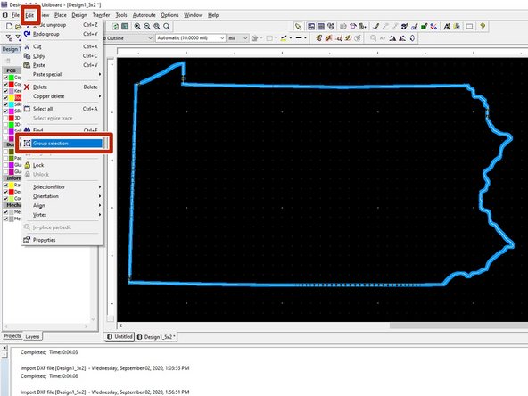
Press CTRL A to select all of the elements of your outline. Choose Edit -> Group selection from the toolbar.
-
Your outline is now one continuous object. You can move it to wherever is convenient on your screen. Try to keep the origin, designated by the small white crosshairs, near the bottom left of your yellow board outline.
-
You may now begin placing your components and running traces.
-