-
-
This tutorial is an introduction to object manipulation within the slicer software Superslicer.
-
Because there are many factors that are in need of consideration, this is not a step-by-step tutorial, rather it is informational. Frequently the optimal orientation is up to the user and their preferences.
-
Further questions can be directed toward the Lab Director.
-
-
-
The object manipulation tools are found on the left side of the window. These include the following tools in order starting from the top: Move, Scale, Rotate, Place on Face, Cut, Paint-on Supports and Seam Painting.
-
There are additional tools which are located above the object. These tools may become useful in certain circumstances.
-
All tool names will appear when you hover the cursor over each tool button.
-
To use each tool:
-
Left click on the object highlighting it green.
-
Left click on the tool intended for use.
-
Deselecting the object can be accomplished by clicking an area where the object does not exist.
-
-
-
All objects on the build plate should generally be positioned in the center of the bed without intersecting any other objects.
-
To move an object around the build plate, simply left click and drag the object.
-
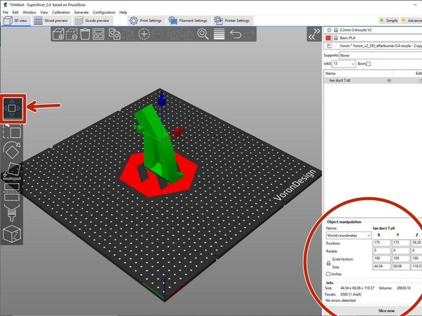
When moving the object along an individual axis, use the first tool "Move" as shown in the image.
-
To use this tool, click and drag the boxes that appear around the object.
-
For more precise control, you can type in a value within a text box. This is located near the bottom right side of the window in the section"Object manipulation".
-
An automatic arrangement tool can also be found on the top of the viewing window.
-
-
-
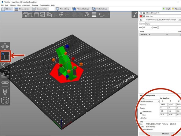
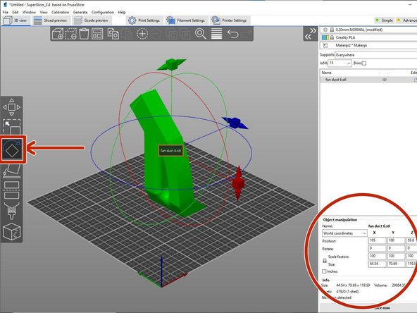
The second tool "Scale" is used to scale the object either uniformly or along a chosen axis.
-
Usually, scaling is not needed. If the object is not the size that is expected, go back to the CAD program (i.e. Onshape), and export the stl file in mm.
-
The "Scale" tool can be used by clicking and dragging the squares around the object.
-
The corner squares scale the object uniformly whereas the squares along each axis scales the object along that axis.
-
To reset scaling or provide more precise scaling, use the object manipulation section found near the bottom right of the window.
-
-
-
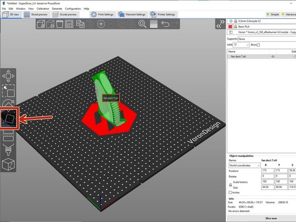
The 4th tool "Place on Face", is used to align a face with the build plate.
-
To use this tool, select the highlighted regions that appear on the object.
-
There are some considerations when choosing a face. These include:
-
support material, speed, surface texture, etc.
-
In most cases minimizing support material is the reason for choosing a certain face.
-
A discussion on what support material is and why it is needed can be found in the Support Material tutorial.
-
-
-
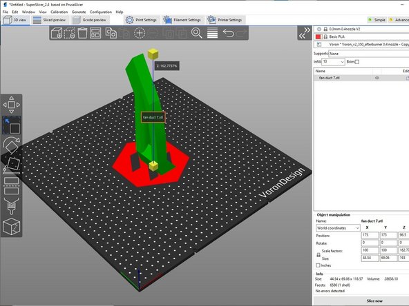
The 3rd tool "Rotate" is used when a particular angle orientation is needed rather than a particular face.
-
Note that using this tool will likely generate more support material as discussed in the Support Material tutorial.
-
To use this tool, click and drag one of the boxes appearing around the object to rotate the object around a desired axis.
-
As before, if an exact degree is needed, typing in the value into the corresponding text box within the Object Manipulation section will work as well.
-
-
-
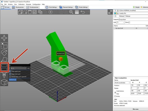
The "Cut" tool shown in the image is used to split the object in a chosen cross sectional z axis position.
-
To use this tool, click and drag the box for a visual location or type in a z axis position in the text box appearing next to the tool button.
-
Using this tool creates two objects that can then be manipulated separately.
-
This is useful when gluing the separate pieces together after the print is complete reducing the support material.
-
-
-
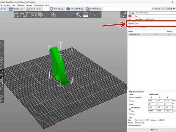
Normally, Superslicer automatically generates support material where its needed. Why support material is needed is discussed in the Support Material tutorial.
-
To control if and how automatic support material is generated, a drop down selection is found near the top right of the window just below the printer selection.
-
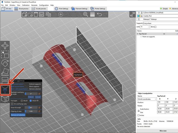
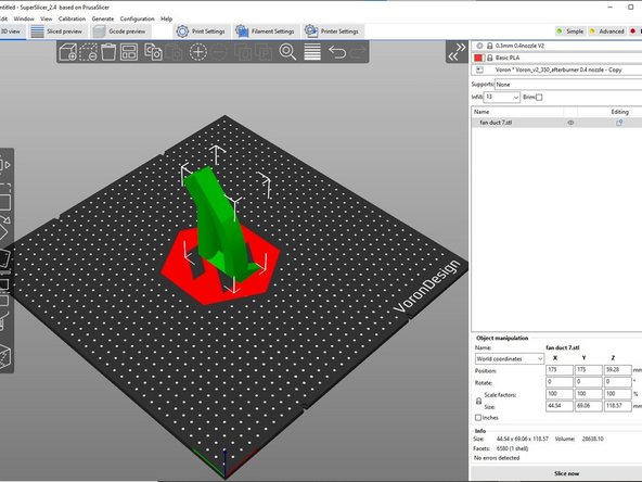
The tool "Paint-on Supports" can be useful if additional customization to support material is needed.
-
There are many options within this tool including manually painting on a surface "brush" or selecting a surface "Smart fill".
-
Left clicking highlights a surface in blue which indicates that surface should have support material.
-
In contrast, right clicking highlights a surface in red indicating that the surface should not have support material.
-
-
-
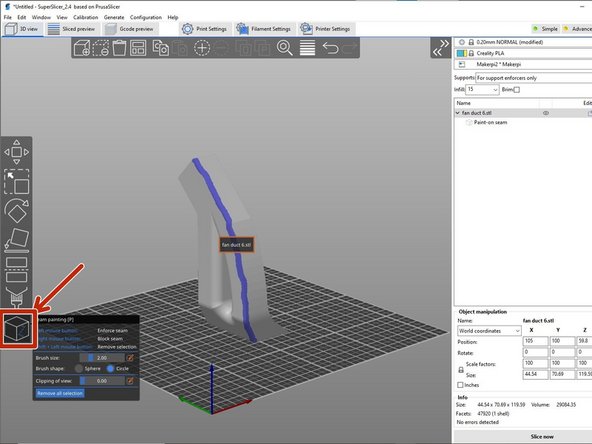
The tool "Seam Painting" is used to further refine surface imperfections.
-
On the outermost wall of each cross sectional layer the nozzle has a stopping and starting location. In this location a slight imperfection is created called a seam.
-
The seam location can be controlled using this tool.
-
Usually, the location for the seam is chosen on the back of an object where it is less likely to be seen or easily noticed.
-
-
-
As the user interacts with these tools, their usefulness increases.
-
This tutorial is only an introduction to the tools within Superslicer.
-
Any comments or questions can be directed toward the Lab Director.
-