-
-
This tutorial explains the need for support material when FDM 3D printing.
-
Parts of this tutorial were generated using Gemini AI.
-
Any further questions after completing this tutorial can be directed toward the Lab Director.
-
-
-
FDM (Fused Deposition Modeling) 3D printing builds objects layer by layer using a heated nozzle that melts and extrudes thermoplastic filament.
-
Support material is needed to physically support overhanging sections of a print that would otherwise sag or collapse due to gravity.
-
However, support material should be used sparingly for the following reasons:
-
Increased time for printing and post processing of your object.
-
Increased material consumption.
-
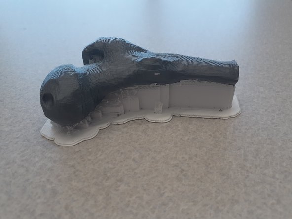
Scaring where support material touches the object.
-
-
-
Removing support material can be difficult depending on the extent.
-
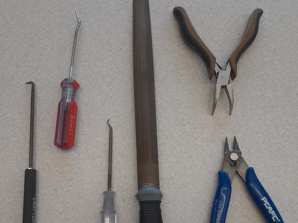
Ideally removing support material requires no more effort than pulling it off with your hands. If this will not work, the following tools may help:
-
Pliers of all types
-
Precision hooks and picks
-
Files or sandpaper
-
Remember that when using these tools, protective goggles and gloves are required.
-
Also remember to use tools with the force going away from you and your hand.
-
-
-
The main considerations involved when trying to minimize the amount of support material include:
-
Object orientation
-
Bridging
-
Overhang angle
-
Object design
-
Support material type
-
-
-
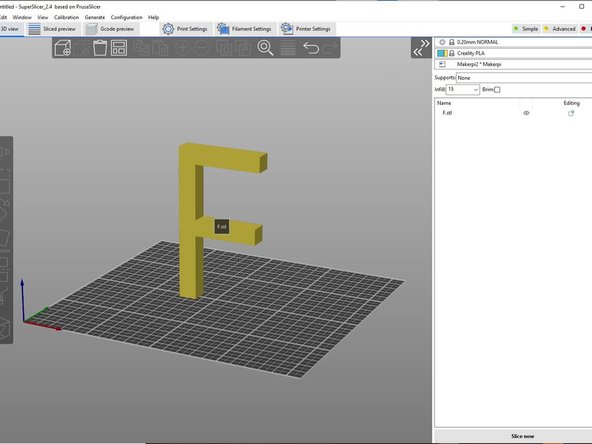
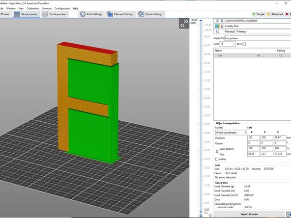
Object orientation is the first option since it's the easiest option to change. Consider a 3D capital letter F as shown in the first image.
-
The image has the object highlighted in yellow while the support material is in green.
-
This object has two overhangs that are impossible to print without support material when printed in the upright orientation.
-
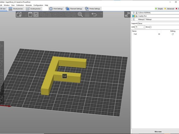
However, if the object is laid down, it will print well without support material as shown in the second image.
-
There may be more than one face which would negate the need for support material.
-
Keep in mind that the object needs to be perfectly flat on the build plate to print successfully. Even when the object is oriented close to flat on the build plate, the print will fail. Use the "Place on Face" tool when selecting a face to lay onto the build plate as discussed in the tutorial Object Manipulation.
-
-
-
Bridging refers to the process of extruding filament across a gap to create a connection between two solid parts of the print without using support material.
-
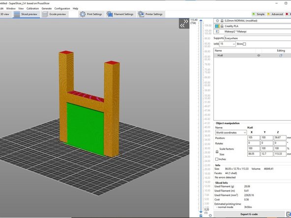
The first image shows a 3D capital letter "H" generated with support material which is normally needed.
-
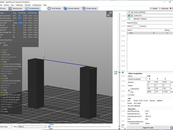
In the second image is a cross section of the "H" without support material being printed where bridging is possible. Notice that the thin blue line is a single extrusion from the nozzle that is able to connect to both posts of the "H" negating the need for support material.
-
There is a limit to the possible length bridging can go which depends on the printer and print settings.
-
When bridging, there is some sagging that will occur due to gravity.
-
Customizing where support material is generated and where it shouldn't be generated is used within the tool "Paint-on Supports" and is discussed in the tutorial Object Manipulation.
-
-
-
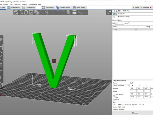
Overhangs can actually be printed if it is at an angle. Consider a 3D capital V as shown in the first image. This object can be printed given two assumptions.
-
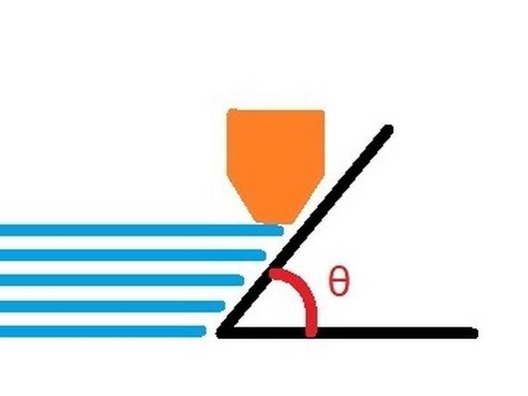
First is the overhang angle. The second image shows an angle between the objects surface and the build plate. Notice that there is still material that the extruded filament can attach to underneath the nozzle on each layer. However, there is a threshold angle which is too steep to print successfully and requires support material.
-
The general rule of thumb is that a 45 deg angle will print well, however steeper angles may be possible.
-
Secondly is the ratio of how tall and thin an object is compared to the base cross-sectional area that attaches to the build plate. The object needs to securely grip onto the build plate during printing.
-
-
-
Incorporating object orientation, bridging and overhang angle into the initial design of the object can help achieve a successful print.
-
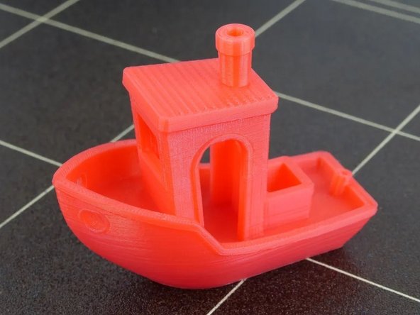
Consider a commonly used benchmark print the "3D Benchy" designed by CreativeTools shown in the first image which incorporates these features into its design.
-
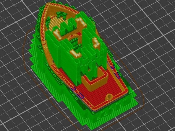
All of these features make it possible to print this Benchy without support material. If the 3D Benchy was printed with support material, it would be difficult or impossible to remove due to the various intricate details.
-
As an example, the next image is that of a cross section of the 3D Benchy with support material generated.
-
-
-
Normally support material is generated in a grid type pattern, however there is another option namely tree supports.
-
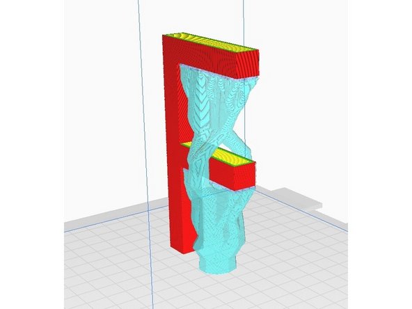
Tree supports as shown in this image have the unique capability of going around the object.
-
The 3D letter "F" shows the tree supports going around the bottom overhang so that it can support both overhangs.
-
This allows for easier removal and less scaring when support material would otherwise be generated on the surface of the object.
-
-
-
There are more resources online about support material including this link.
-
Other useful considerations not covered in this tutorial include:
-
Dissolvable support material
-
Space between support material and object
-
Support material size and shape
-
Removal techniques
-
Any further comments or questions can be directed toward the Lab Director.
-
Almost done!
Finish Line


