-
-
Mold making is and extensive field and has a broad range of possible complexity.
-
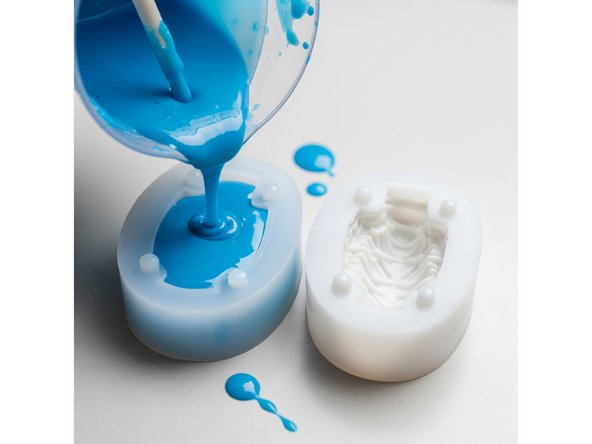
This tutorial goes through the basics of mold design commonly used in the BME department including starting with an STL file and ending with a 3D printed rigid mold. This tutorial does not cover all aspects of mold design.
-
This tutorial has been made by Jacob Nickle along with Gemini AI
-
-
-
The following principles are discussed in this tutorial:
-
Design Considerations
-
Detail Capture
-
Undercut / Draft Angle
-
Sprue / Vent
-
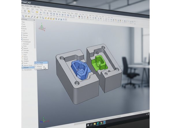
Software Used for Mold Design
-
-
-
Is the object in a physical form or digital file?
-
If it is already in a physical form, it will be used as a master to create the mold.
-
If it is a digital file such as an STL, then the mold could be digitally made and then 3d printed depending on tolerance needs.
-
What is the shape of the object?
-
The shape dictates if a one-part mold is sufficient or if a parting line, or other complexities are required.
-
There are many resources for simple mold making using Smooth-on products that can be found in this link.
-
This tutorial goes beyond smooth-on tutorials and assumes the object is in a digital form and requires more than just a one-part mold. Additionally it will be assumed that a rigid 3d printed mold works best.
-
-
-
Designing a mold requires the capturing of necessary details of the object.
-
The best mold material is a necessary consideration due to the following reasons:
-
Cured material can shrink.
-
Low viscosity may be needed for high level of detail capture.
-
Compatibility between the mold and cast material.
-
Adherence between the mold and cast material.
-
Furthermore, techniques such as vacuum degassing, pressure casting, pouring and vibration may help to capture further detail as needed.
-
-
-
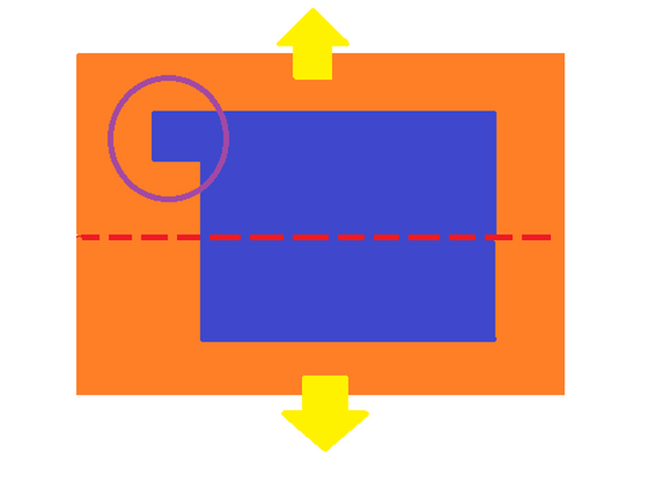
When designing a mold, the cavity needs to be positioned such that the mold can be removed once the cast part fully cures. If the mold is rigid as assumed in this tutorial, two object shape features need to be considered namely any potential undercuts or any needed draft angles.
-
An undercut occurs when the objects shape would interfere with the mold when attempting to remove the object.
-
Consider the simplified 2D 2-part mold in the image. The mold is orange and the object is blue. Notice the red dotted line. If the 2-part mold was split at the red line and the mold was rigid, removing the object from the mold would be impossible due to an undercut as highlighted by the purple circle.
-
The red dotted line is what is called a parting line. Redesigning the mold such that the parting line was positioned within the region of the undercut, would allow the mold to be removed.
-
Even if the undercut did not exist in the previous example, removing the object from the mold could be difficult or impossible since the object is perpendicular to the parting line. Adding a slight outward angle to the object up to the parting line could resolve this issue. This is called a draft angle.
-
-
-
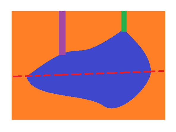
The sprue is the primary channel that acts as the entry point for the resin material into the mold. In this case it enters the mold cavity directly.
-
Consider another simplified 2d example in the image. The orange is the mold, the blue is the object, and the purple is the sprue.
-
Notice that the sprue enters the object further down than the highest point of the object. If a simple pour technique were used, the resin would not go above the sprue entry point unless a vent(green) were created allowing the air to escape.
-
Furthermore, injecting the resin may become necessary for the cast liquid material to reach all parts of the cavity. Any area where air could be trapped requires some sort of vent.
-
-
-
If the object starts as an STL file, the general design progression in CAD software is followed:
-
Convert the stl into a solid part.
-
Create an encompassing mold part and split it at the best location for a parting line.
-
Perform a boolean operation removing the overlapping area of the encompassing part and original object.
-
Create a sprue, vents, registration keys and other details as needed.
-
Note that the sprue may require a larger size or custom shape depending on how the liquid cast material will enter the cavity.
-
Create a feature to reduce the possibility of the liquid cast material leaking out of the cavity.
-
Export as an STL, 3D print and then modify for improvement as needed.
-