Introduction
This is the guide for how to make, code, and develop the line-following robot.
Adapted from University of California, San Diego Jacob School of Engineering. Developed by Karcher Morris & Dr. John Eldon. Original lab created by Professor john Eldon, Professor Vikash Gilja, Professor Drew Hall, Professor Truong Nguyen.
-
-
If you decide to work on a personal computer, download Arduino from their website. Arduino Link
-
If you decide to work on a lab computer, they should have Arduino on them.
-
-
-
Objective: The objective of this challenge is to set up the potentiometers and ensure that turning the knobs does change the values printed. These values will later be used to control the PID.
-
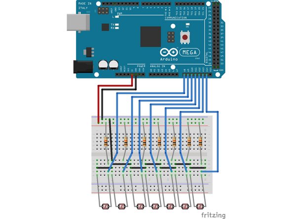
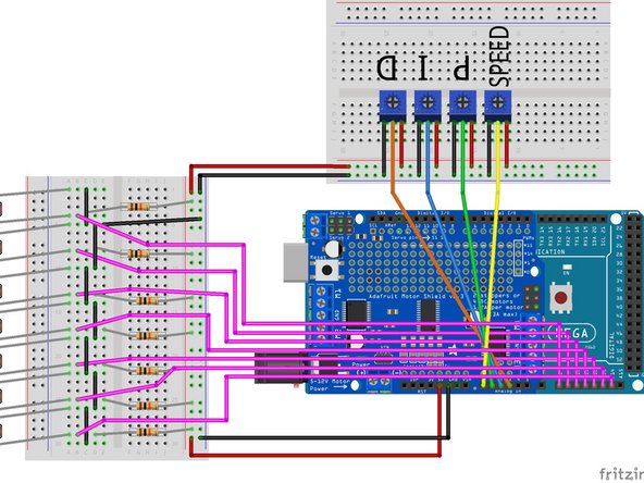
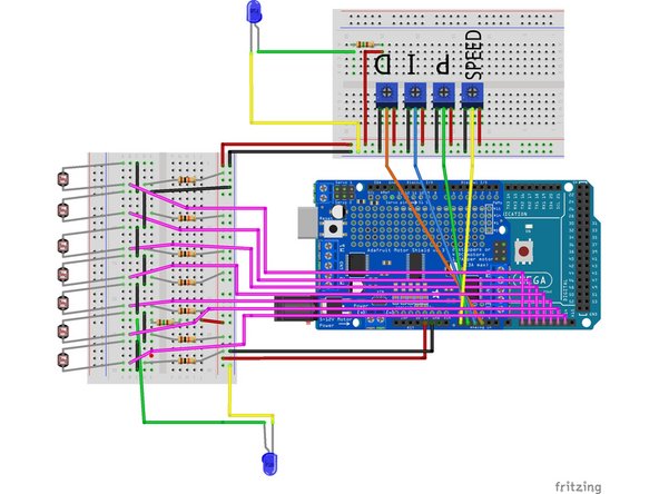
For the first challenge, set up potentiometers on a bread board and follow the wiring diagram shown on the left. Then plug the Arduino into your computer.
-
Use the DRIVE to download the file named Potentiometer_code.ino Then open and upload the code to your Arduino board using your A-B cable.
-
Test this to ensure it prints the potentiometer output to the serial monitor. Remember that a potentiometer acts as a variable resistor.
-
If this is not working refer to the Tips Sheet.
-
NOTE: This challenge is not setting up your PID controller, it is only setting up a way to interface/change your Speed, P, I, and D coefficient values (variables) without the need to re-upload new code to your Arduino each time.
-
-
-
Do counter clockwise or clockwise twists of the potentiometers increase the value printed to the serial monitor?
-
What are different ways to switch it from counter-clockwise to clockwise or vice versa? Change the given code to do this.
-
-
-
Objective: The objective of this challenge is to wire the photoresistors which will be used to detect the line on the floor.
-
Keep the breadboard with the potentiometers in tact, but unplug only the wires which go into the Arduino and use your second breadboard for this challenge.
-
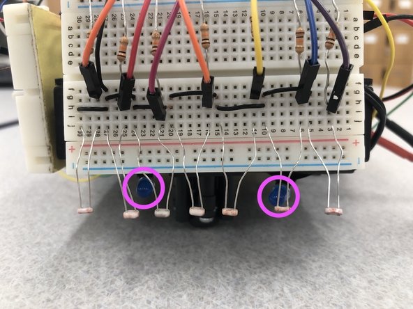
Using the 10kΩ resistors, develop multiple voltage dividers, by following the schematic to the left. Instead of variable resistors being made of knobs like in challenge #1, they are now sensors that change resistance dependent on light.
-
Once you have the board set up, use the code in DRIVE titled Photoresistor_code.ino where you can read the values from each of your photoresistors and print them to the serial monitor.
-
-
-
Try placing the photoresistors close to different colored surfaces and then try it out on a line.
-
What is the best distance for your sensors to be away from the surface to properly differentiate when the sensors are hovering over black or white?
-
How does surrounding light or shadows affect the readings? Do they get higher or lower?
-
-
-
Objective: The objective of this step is to build the cart which all of the other components will attach to.
-
Using 2 wheels, 2 motors, and the caster ball we will now assemble the bottom portion of the cart. (Disregard the given pamphlet instructions while building the cart, we will use only it's part numbers as a reference)
-
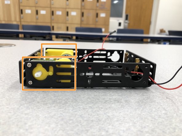
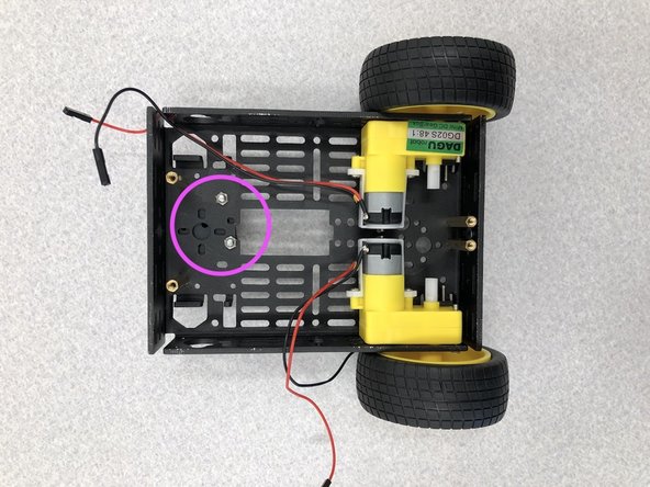
Attach only the BACK TWO DC motors to the cart. (Required parts: 2, 3, 7, 8)
-
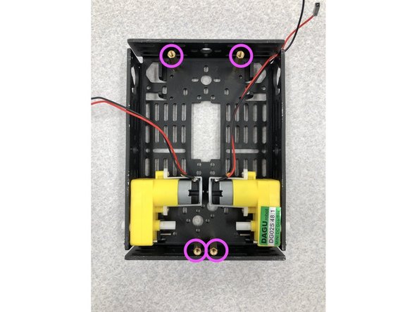
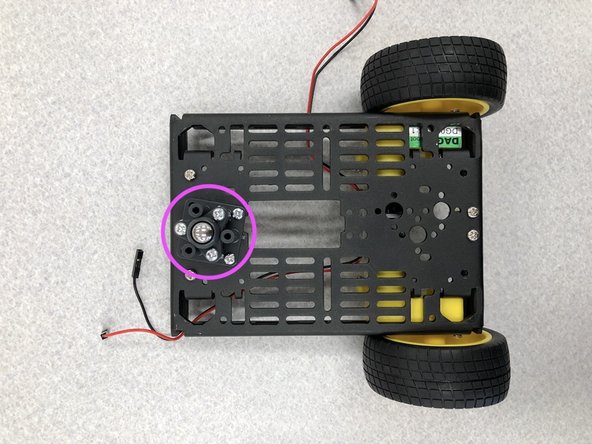
Screw the distance holders and M3*8 screws to the locations marked in pink in the images to the left. (Required parts: 5, 9)
-
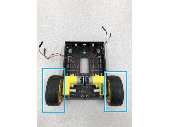
Now attach the wheels to the motors. (Required part: 4)
-
-
-
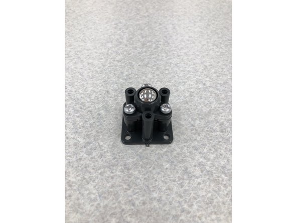
Objective: The objective of this step is to create the caster which replaces the two front wheels. This way we will only need to worry about the back two motors.
-
Now it is time to build the caster. Follow the given directions for the 25mm height caster. It should resemble the image to the left once finished.
-
Attach the caster to front of the cart using the given screws.
-
-
-
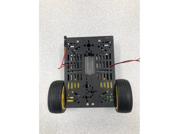
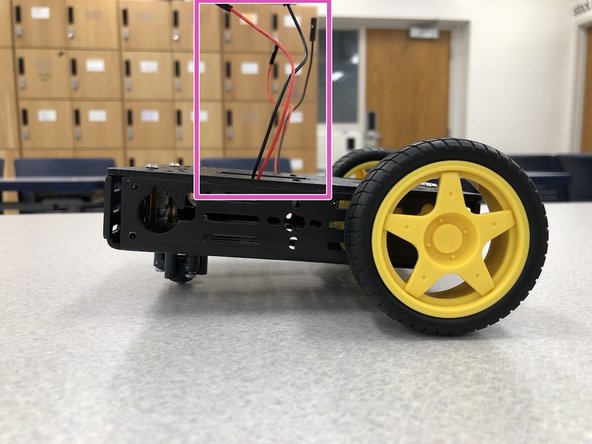
Put the chassis top onto the cart and screw it closed. (Required parts: 1, 9)
-
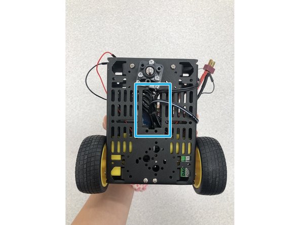
Make sure to pull out the black and red wires which power the motors.
-
-
-
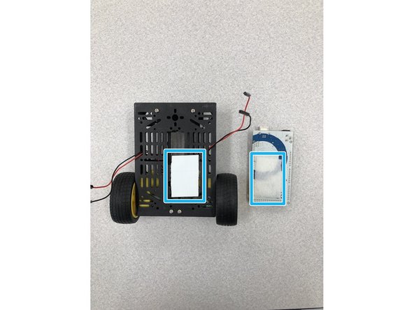
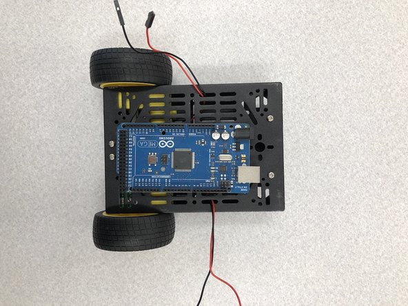
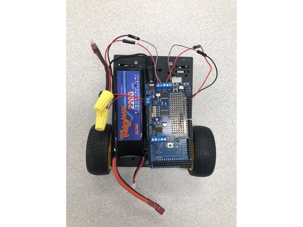
Use the Velcro tape to help fasten the Arduino to the cart to keep it from sliding around.
-
NOTE: It is probably most helpful to place the Arduino on the right side of the robot leaving enough space for the LiPo Battery to fit on the left side. Also be sure to keep enough space between the front of the cart and the Arduino ports so you can easily plug and unplug the A-B Cable.
-
-
-
Objective: The objective of this step is to use the motor shield as an attachment to our Arduino to control the motors on the robot.
-
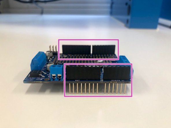
The header pins included with the Adafruit motor shield will not be used in this tutorial. Set them aside and instead use the stackable Arduino headers provided to you. These stackable headers are shown here in the image.
-
Solder the stackable headers in place on the motor shield PCB. Insert the male pins of the headers from the top of the PCB (the side with components) and solder the pins on the bottom side. Make sure the black plastic female part of the headers are sitting flush with the top of the PCB before soldering.
-
Keep the stackable headers as straight as possible while soldering. Failure to keep the headers straight will prevent the shield from properly attaching to the Arduino.
-
-
-
Objective: Anytime you use an attachment to an Arduino, you must add the proper libraries to your code.
-
Use the links provided at the top of the code provided in the file named MotorDriver_code.ino in the DRIVE to download and install the Adafruit motor shield library for Arduino.
-
Without the motors connected, but with the motor shield attached to the Arduino, ensure the motor driver code compiles and uploads without error.
-
-
-
Objective: The objective of this step is to now put together all of the breadboards and other components that we have set aside and integrate them to create your robot.
-
Looking at the diagram on the left, connect your motors to M1 and M2 on your motor shield using the terminal blocks. For help using the terminal blocks refer to this link
-
We will use the LiPo battery to power both the motor shield and the Arduino in this step.
-
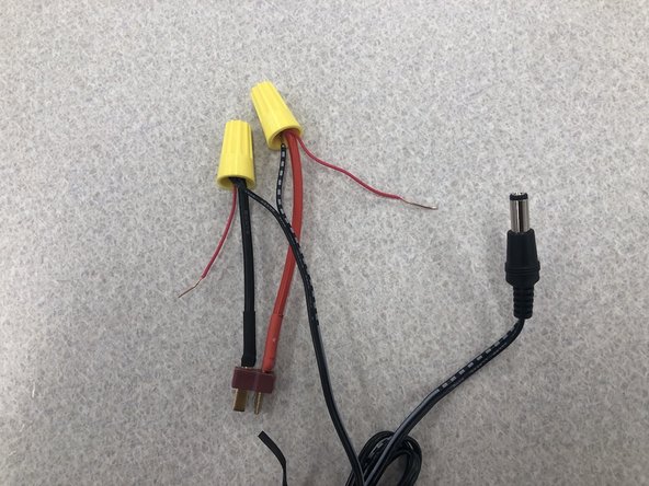
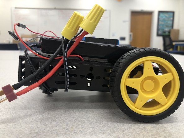
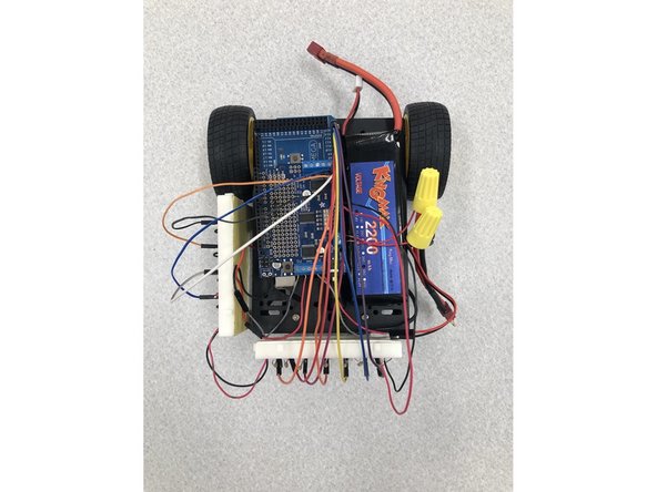
Using two wire nuts, we will merge a single spare wire, the barrel plug cable, and the t-plug cable together as shown in the image to the left. NOTE: Strip at least 1/2 inch of all wires before using the wire nut.
-
The striped wire on the barrel plug is power and the solid wire is ground.
-
If you do not know how to use a wire nut please refer to the this youtube video
-
-
-
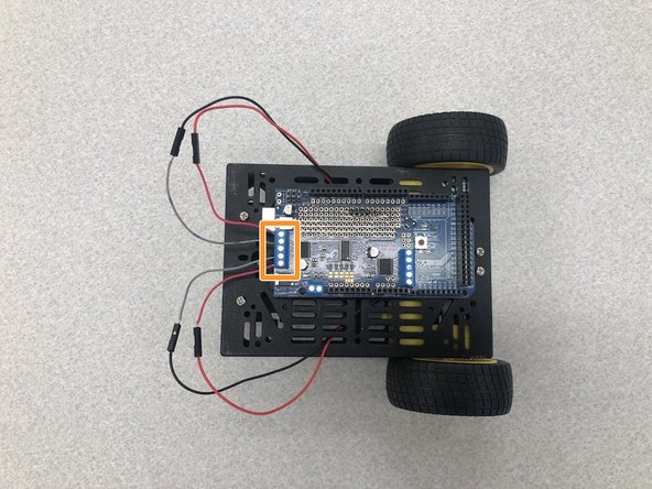
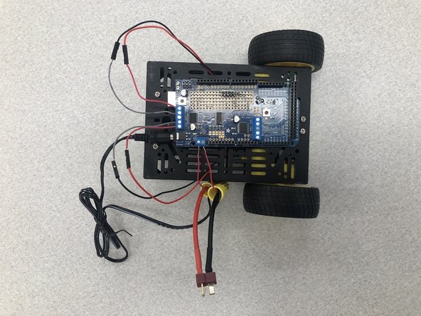
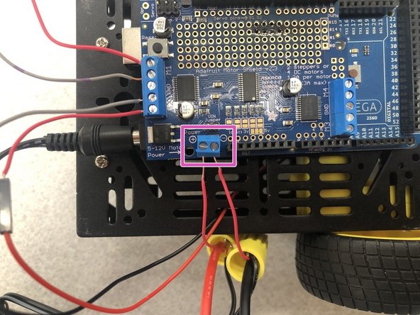
Now we will plug the barrel plug into the Arduino Mega and put the spare wires into the terminal blocks of the motor shield.
-
Polarity matters! Make sure that power and ground are plugged in accordingly. DO NOT use the battery yet!
-
Now take the excess barrel plug wire and tuck it into the robot underneath to keep from tangling.
-
-
-
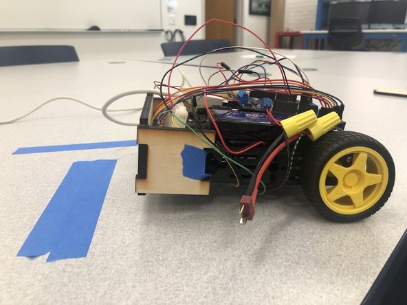
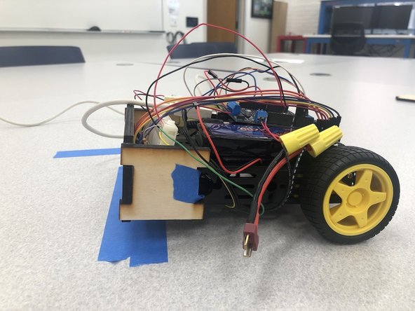
Use velcro tape to attach the LiPo battery to the top of the robot.
-
Now plug in JUST your LiPo battery to the t-plug and your robot should begin to move in a straight forwards after a few seconds, then move backwards.
-
When powering the robot, it may move pretty quickly so avoid testing on elevated surfaces.
-
If your robot does not move, try to upload the code from step 11 to your Arduino again. DO NOT plug the Arduino into your computer and the battery at the same time.
-
NOTE: If you notice that one wheel moves forward and one wheel moves backward, or both wheels move backwards when it should be moving forward, simply change the polarity of wires coming from your motor shield from M1 and M2 by inserting the black wire where the red wire is and vice versa.
-
-
-
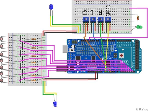
Now follow the schematic given and carefully plug in the components back onto the Arduino and shield as we did in Challenges #1 and #2.
-
To secure the breadboards, use velcro tape to attach them to the robot.
-
Run each of the programs from Challenges #1-#3 individually. Does each potentiometer work? Does each photoresistor work and sense the difference between a black and white surface? Does the cart still drive forward and backward? Do not move on if your robot does not pass all 3 of these tests.
-
-
-
Objective: The objective of this step is to mitigate the problem of ambient light changes and shadows which may impact what the robot detects to be the line vs. the floor by including 2 blue LEDs as backlights for the photoresistors.
-
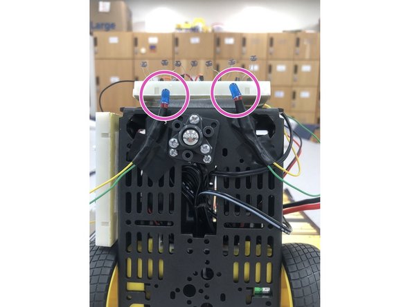
Use the 5V rails from either of the breadboards that have already been implemented to power the LEDs.
-
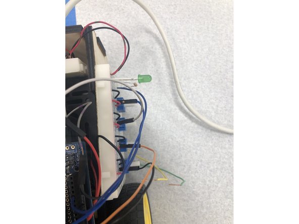
NOTE: Remember that LEDs have polarity, the green wire is the positive side, the yellow wire is the negative side as shown in this diagram. Be sure to use 150 ohm resistors in series with the LEDs in order to limit the amount of current drawn from the Arduino.
-
You will need to solder longer wires onto the LED leads in order to place the LEDs appropriately on your robot and still make electrical connection with the breadboards.
-
After soldering wires onto the LED leads you may wish to apply heat shrink tubing to the solder joints in order to prevent any short circuits.
-
Now tape the wires attached to the LEDs to the bottom of the cart facing the photoresistors. Try to place these evenly apart from one another and both the same distance away from the photoresistors
-
-
-
Objective: For this portion of the challenge, you will create a light shield to further mitigate the problems of shadows and light changes.
-
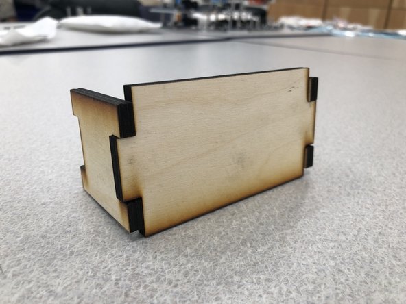
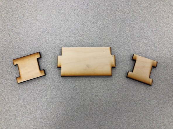
For this step you will laser cut 3 pieces of wood to create the light shield.
-
-
-
Objective: The objective of this step is to learn to laser cut your shield.
-
There are 3 pieces to the light shield which fit together like a puzzle piece. The file you will be using with the GlowForge laser cutter is named lightshield1. Using this file, follow the Dozuki tutorial for laser cutting here.
-
Once you have laser cut the pieces, use the wood glue and some clamps to put the pieces together.
-
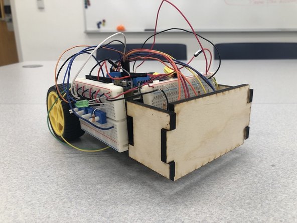
Using electrical tape or velcro tape, stick your light shield to the front of your robot. NOTE: one of the side pieces is smaller than the other, it is meant to go on the side of the robot with the potentiometers.
-
-
-
Objective: The objective of this step is to calibrate your photoresistors since the readings can easily change due to alterations in positioning and differences in lighting.
-
The main goal with your calibration is to take the possible readings from each photoresistors, and map those readings to a more uniform measure making it more clear where a black line may be located.
-
Before uploading and running the new code, you will first add an indicator LED to make the high/low output on pin 13 more visible. You can do this by following the schematic to the left and putting a green LED in series with a 1kOhm resistor and connecting it to ground on one end and to output pin 13 on your motorshield.
-
-
-
The indicator light lets you know what stage of calibration you are in. Read all of the following directions before attempting.
-
Plug in the LiPo battery to the robot and while the connected LED is blinking slowly, place the photoresistors attached to the breadboard and cart over a white surface.
-
After a few seconds the LED will blink quickly and at this point it is important not to touch the cart or cast any shadows over it because it is finding the nominal photoresistor reading of each pin for what correlates with pure white.
-
The LED will then blink slowly again giving you time to move the photoresistors over a pure black surface or line. Ensure that each photoresistor is fully over the black surface.
-
Again, after a few seconds the LED will blink quickly and again it is important not to touch the cart or cast any shadows over it because it is finding the nominal photoresistor reading of each pin for what correlates with pure black.
-
Open the serial monitor code before uploading the calibration file. Find the code in DRIVE titled Calibration_code.ino and upload it to your board. Perform the calibration by following the steps described above.
-
-
-
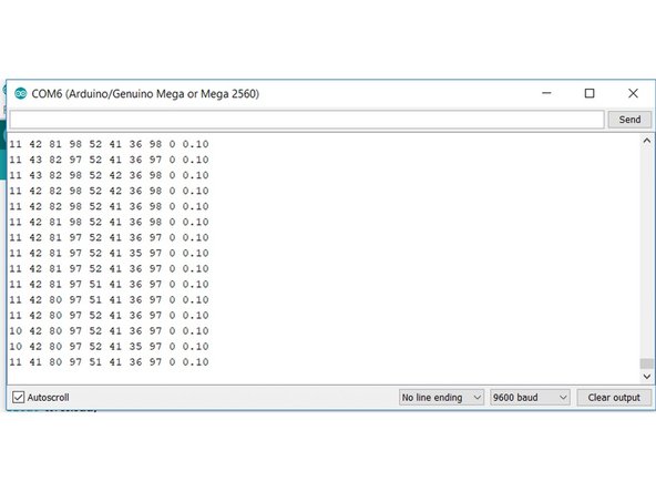
Test if your calibration was successful by checking the serial monitor. The first seven values are for the photoresistors, then the serial monitor shows the maximum, minimum value and an error calculation. You should clearly be able to see the values change when facing the floor vs. the tape.
-
Values should be between 0 and 100 with ~0 for the surface you calibrated first and ~100 for the 2nd surface calibrated. If you can not get reliable values, you may need to disconnect the blue LEDs.
-
e.g. In the image to the left you can see that the dark line was beneah the third and fourth photoresistors.
-
-
-
Objective: The objective of this step is to write your own PID control code which will keep the robot from veering off of the line.
-
Prior to completing this step, it is highly recommended that you read the given Review on PID Control document here.
-
For the PID Turn Control you will be writing all of the code yourselves. The step by step directions have been given here as well as the required questions for Challenge #7.
-
Now that you have written the code for the PID Control and ensured it compiles without error.
-
-
-
You have been given the skeleton code for the overall line following robot titled Line-Following-Robot_Skeleton_Code.ino in the DRIVE, follow the directions and write/insert the rest of the missing code as well as your PID Control code.
-
Now verify the code to ensure it compiles without errors, then upload the code to your board. If you come across errors, be sure to check for helpful tips here.
-
NOTE: Remember to unplug your LiPo battery any time you are uploading code to your board.
-
-
-
Remember to answer and submit the questions given at the bottom of the PID Turn Code document. They can be found at the bottom of the PID_Turn Code document.
-
-
-
Objective: The objective of this step is to test the robot to see if it follows the line and does not veer off.
-
When uploading your overall line following code remember that the code calibrates every time you run the code. Meaning you will have to follow the steps from Challenge #6 pt. 2 with the indicator LED prior to testing the robot on a line.
-
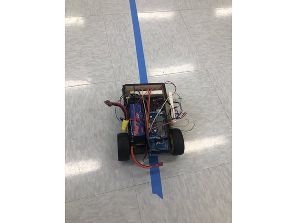
Now using some lines of a dark color tape as tests, see if your robot does in fact follow a line. Note: If your robot seems to be moving slower than usual, this usually means the LiPo battery is running low on charge.
-
Congratulations! You've finished your line following robot!
-