
Introduction
This guide will walk you through the steps of assembling a DAMNED device. You will be provided with the BOM (bill of materials) and the guide will explain each step of assembly. This guide assumes you have completed all prior steps of 3D printing and laser cutting parts and soldering components to the PCB.
-
-
Confirm you have everything on the bill of materials (BOM).
-
In addition to these parts you will need the items you assembled during the previous Design Assignments:
-
Populated PCB
-
3D printed pieces including the shell front, shell back, and motor arm
-
Laser cut pieces including the LED ring base, ring mount bottom, ring mount top
-
-
-
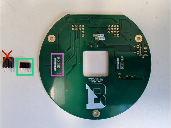
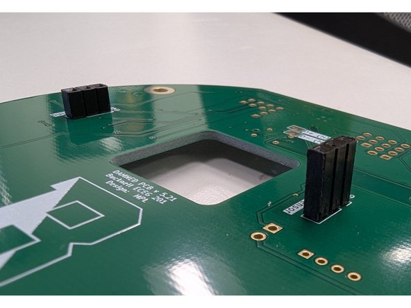
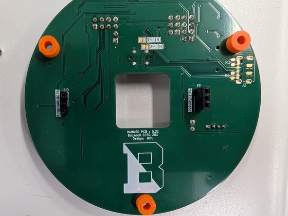
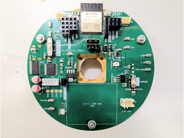
There are two 3-socket headers in your parts kit. Locate the shorter of the two headers. This socket will mount on the bottom side of the PCB and be soldered on the top side. See the green highlighted connector in the first image.
-
Insert the socket on the bottom side of the PCB at location J10 (purple highlighted position). Hold it in place with some blue tape and make sure that it sits flush against the PCB surface.
-
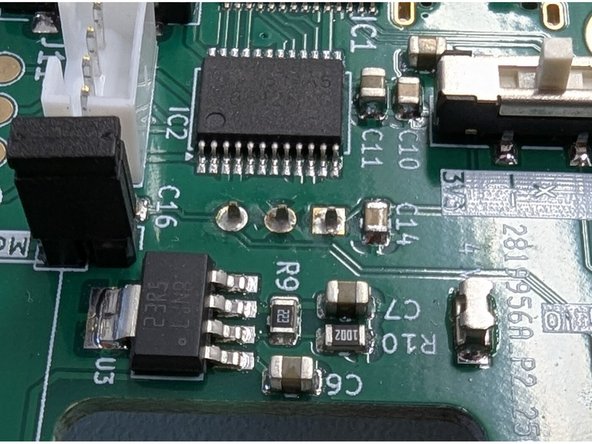
Flip the board over and carefully solder the three connections on the top side of the board. Ask for help if you cannot solder the pins without bridging.
-
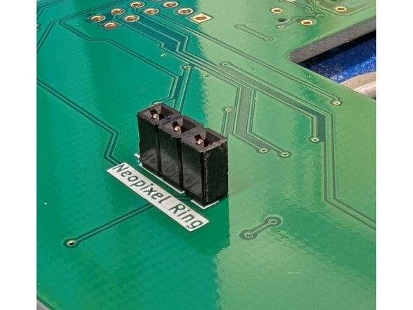
When you're finished the solder joints should look similar to the last photo here.
-
-
-
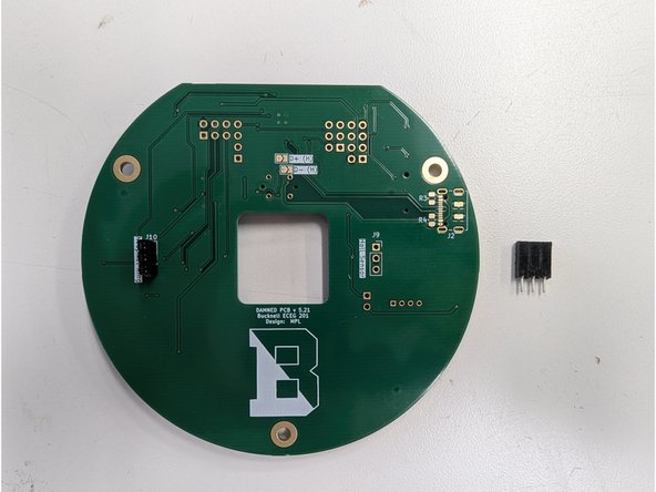
Locate the remaining, taller 3 socket header from your parts kit.
-
Similar to the previous step, place the socket on the bottom side of the PCB. Hold it in place with some blue tape.
-
Solder the 3 solder header on the top side of the PCB.
-
When finished, your joints should look like the final image here.
-
-
-
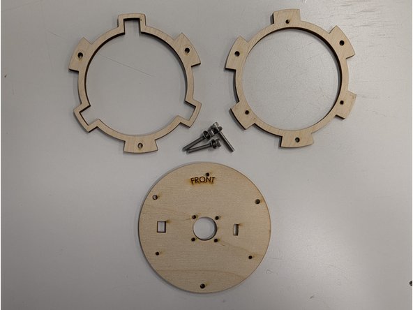
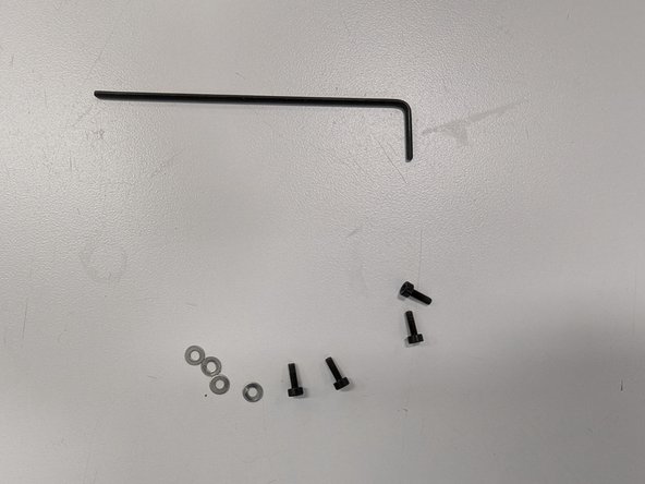
Locate the following:
-
M3x20 bolts (quantity 3)
-
M3 washers (quantity3)
-
your three laser cut plywood pieces
-
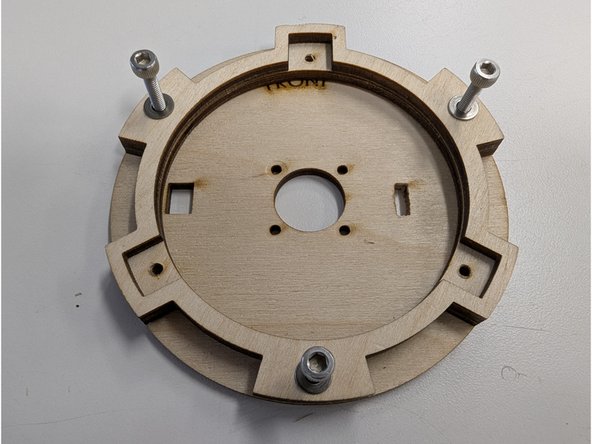
Align the three laser cut pieces in the order shown in the second image. The solid base should be on the bottom of the stack, followed by the ring with six holes in the middle, and the ring with three holes should be on the top.
-
Place the washers on the bolts and place a washer+bolt in each of the three largest holes around the edge of your plywood stack.
-
-
-
Locate the three plastic spacers in your parts kit. Place one spacer on each of the three large holes around the edge of your PCB on the back side.
-
Insert the three bolts + washers through the three large holes.
-
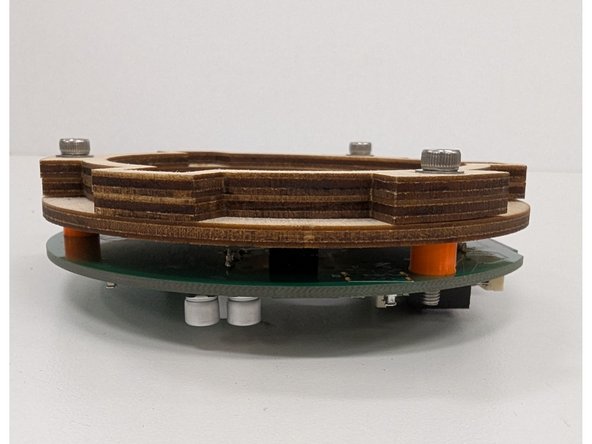
Carefully place the plywood stack on top of the PCB, aligning the bolts with the plastic spacers. The bolts should pass through the plastic spacers and protrude from the front side of the PCB.
-
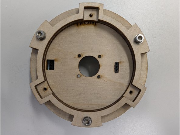
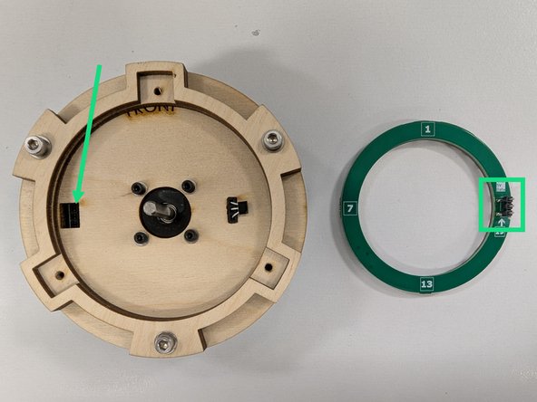
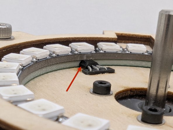
Make sure that the taller 3 socket header for the Hall sensor passes through the corresponding slot in the motor mount base. The socket should be nearly flush with the surface of the motor mount base or protrude slightly beyond it. See the green arrow.
-
-
-
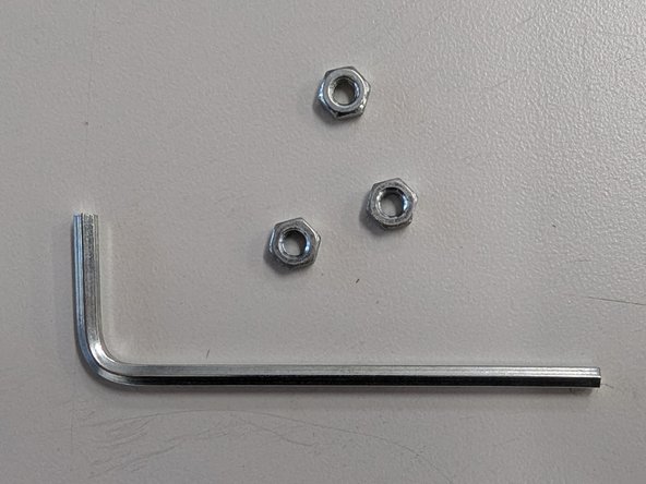
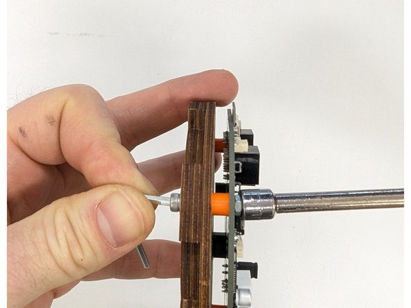
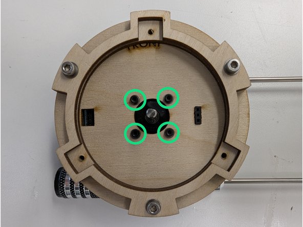
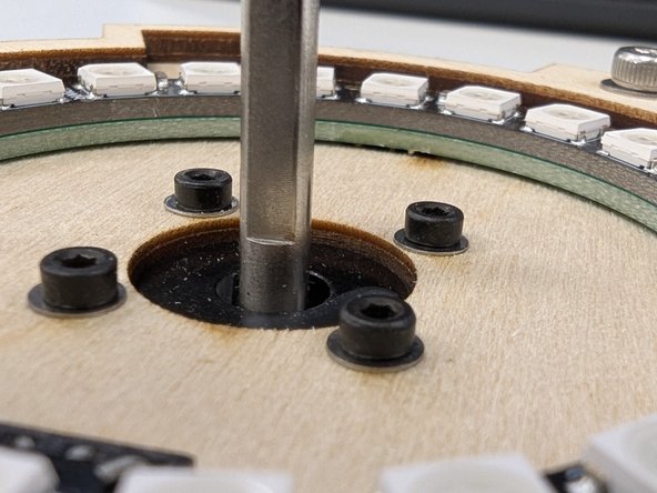
Locate the three hex nuts and the larger of the two provided hex keys.
-
Thread a nut onto each of the three protruding bolts on the front side of the PCB. Hand-tighten all three nuts.
-
Be sure to tighten all three nuts+bolts securely when you're done. Use the provided hex key to rotate the bolts and use a tool to hold the nuts such as a 6 mm hex driver, an adjustable wrench, or a pair of needlenose pliers.
-
-
-
Locate the four M2 bolts, four M2 washers, and smaller of the two hex keys.
-
Place a washer on each of the four bolts.
-
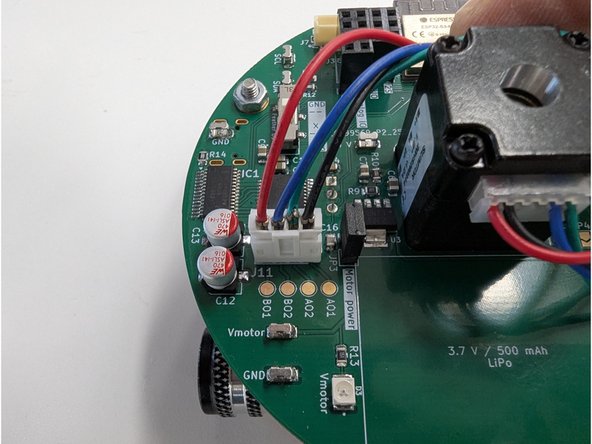
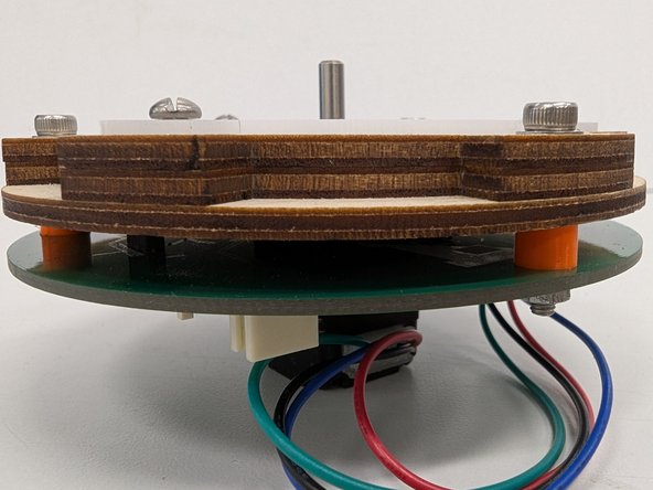
Insert the motor through the square slot in the PCB so that the shaft protrudes out of the wooden motor base. Orient the motor so that the wires point down towards the open space on the PCB.
-
Connect the motor to the PCB using the appropriate connector. Observe the polarity of the connector.
-
Make sure the white plastic wire housing of the motor faces down as shown in the second image.
-
Thread the four M2 bolts into the four holes in the motor mount base from the front of this assembly and secure the motor by using the smaller hex wrench to tighten the four bolts.
-
-
-
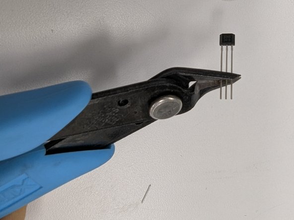
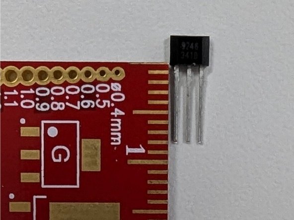
Locate the small 3 pin Hall effect sensor in your parts kit. Trim the leads of the sensor so that they are only 8 mm in length.
-
Use a pair of flush cutters to clip the leads.
-
-
-
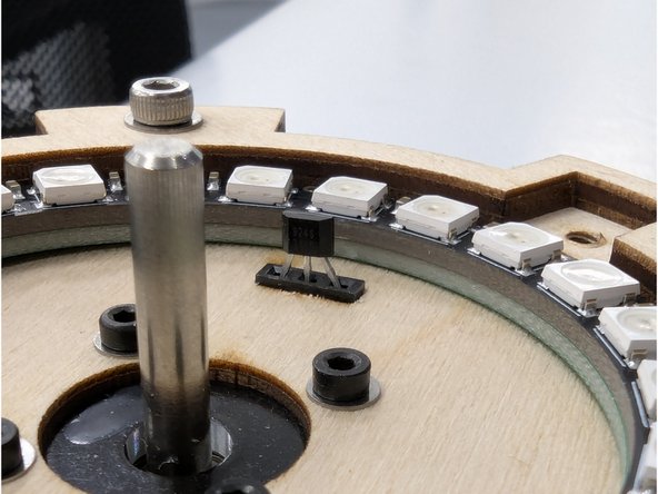
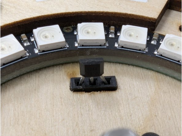
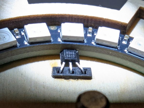
Take the Hall effect sensor with shortened leads and insert it into the corresponding slot in the front of your motor mount base. The leads should firmly and securely insert into the 3 pin socket. Orient the sensor so that the faint white text on the front face points in towards the motor and and away from the outer wooden ring.
-
It may also be helpful to use a pair of tweezers to gently place the sensor into the slot and align the leads. Do not use tweezers to push down on the sensor! Use a stronger tool for applying pressure.
-
With the sensor securely insert, press on the front face of the sensor and apply pressure to bend the black plastic case backwards. This will cause the leads to bend.
-
Bend the sensor back at a 90 degree angle so it sits flush on the wooden motor mount base. See the final image. Note that the white text is facing up and is visible.
-
-
-
Your Neopixel ring may already be smooth along the edges. If not, it may be necessary to sand the mouse bites on the ring to make it fit properly. Grab a file or sandpaper and file these bits until the ring is smooth and fits nicely inside of the laser cut ring.
-
Locate the NeoPixel ring and flip it over so you see the three pin connector. You'll need to insert this connector into the corresponding connector on the left of your PCB assembly, highlighted here in green.
-
Place the Neopixel ring on top of the PCB assembly and look at the assembly from the side. It is important to make sure that the pins on the Neopixel ring align properly with the connector on the PCB.
-
Once you're sure the pins are lined up with the socket connector press down firmly to join the two pieces together.
-
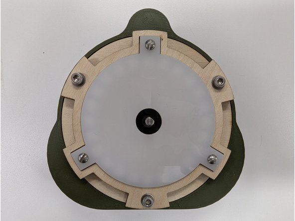
When you're done the Neopixel ring should sit flush with the wooden base. See the second image and confirm there is no gap between the ring or the wooden base around the entirety of the ring.
-
Also confirm that the Hall sensor is still sitting flush with the wooden base.
-
-
-
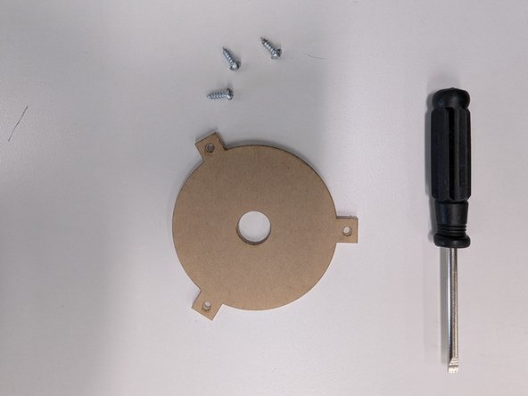
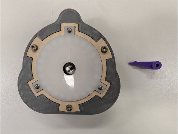
Locate the acrylic diffuser and the three wood screws (pointy ends). You will also need a flat blade screwdriver.
-
Unfortunately, the screwdriver that may have been provided to you in ECEG 201 may not fit the slotted heads of these screws. If that is the case, please use a different screwdriver. You can check the yellow DeWalt cabinet in the Maker-E for other options.
-
Note that you may have to remove a protective film from one or both sides your acrylic diffuser. Once these films are removed your diffuser should be a milky, translucent white.
-
Use the screwdriver to screw the three screws through the holes in the diffuser into the plywood. The holes in the plywood are undersized so you will need to use a little pressure when driving the screws to cut threads into the plywood.
-
Do not overtighten these screws as too much pressure on the acrylic diffuser can cause it to crack.
-
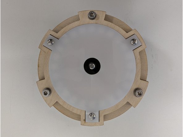
When you are finished with all three screws the acrylic should sit uniformly above the plywood. If there are any areas that are lower than others, slightly loosen the closest wood screw to relieve some pressure on the diffuser.
-
-
-
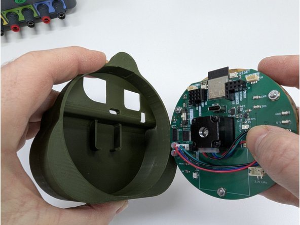
Locate the 3D printed shell back. Orient the shell back such that the opening is pointing up and the flat edge faces towards you. See the first image.
-
Gently insert the PCB assembly into the shell back, keeping the ESP32 module pointing towards the top of the shell back where the two large holes are. The stepper motor wires should be pointing down towards the flat bottom of the shall back. See the first image.
-
Place the shell front onto the shell back, aligning all of the various tabs with the PCB assembly. The magnets in both the shell back and shell front should align properly and the opposite poles should keep the shell front in place.
-
Keeping your hand below the DAMNED project, tip it forward and give it a gentle shake downwards to confirm that the shell front and shell back are prpoerly held together by the magents and the PCB assembly does not pop out.
-
-
-
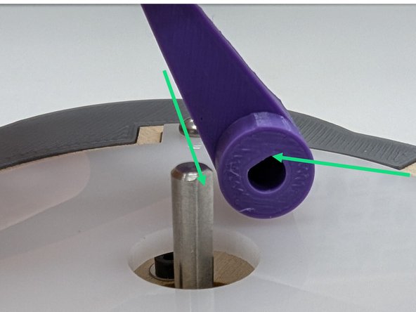
Locate the 3D printed motor arm you designed and printed previously.
-
Notice the D shaped profile of the motor shaft as well as the matching D shaped profile in the motor arm you designed. Orient the arm so that the flat edges of the D profile align.
-
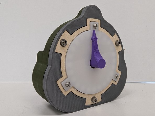
Press the motor arm on top of the motor shaft in the center of the acrylic diffuser. You may need to use a bit of force to press fit the arm onto the shaft. It should be a snug fit.
-
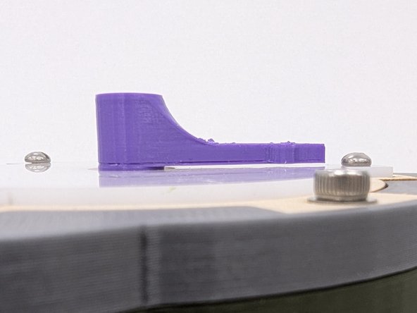
Press the motor arm down as far as it will go. It should sit nearly flush with the top of the acrylic diffuser.
-
There should be a tiny gap between the bottom of the arm and the top of acrylic diffuser.
-
-
-
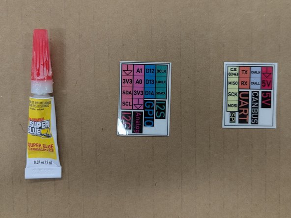
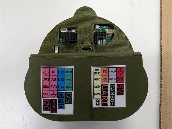
Locate the two laminated labels. Place them on top of some scrap cardboard, plywood, paper towel, etc. You should not perform this step directly on a bench or table!
-
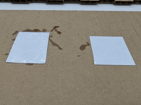
Flip the labels over to the blank white backs. Grab a tube of super glue from on top of the yellow DeWalt cabinet in the Maker-E. Apply a small amount of super glue to back of the labels. Make sure you spread it around the edges of the labels so they won't peel. Smear the glue off the edge onto the protective surface you have underneath.
-
Be careful with the super glue. It is easy to glue your fingers together. You can clean super glue off of your fingers or other materials with some acetone in the wash bottles near the soldering area.
-
Carefully flip a label over and apply it to the back of the DAMNED case. Then apply the second label.
-
Be sure to position the labels as shown in the final example image here! Otherwise it will be difficult to identify pins on your DAMNED during future assignments.
-
-
-
Rotate the motor arm several times in complete circles, both directions, around the face of the DAMNED.
-
If the rotation is completely smooth and you do not feel snapping, or the snapping is inconsistent, you most likely need to redesign or reprint your motor arm.
-
Congratulations! You are done assembling the DAMNED device!
-


Cancel: I did not complete this guide.
9 other people completed this guide.
Team
17 Comments
I had some trouble with connecting the 3D parts together at the end of the tutorial- maybe the sizes could be adjusted a little bit differently.
Elif Tuncel - Resolved on Release Reply
The hardest part is definitely soldering the one lead to the PCB right next to the IC. You really have to be careful.
Hunter Guthrie - Resolved on Release Reply
Great tutorial! Make sure to have all of the glued wood line up correctly for the case to fit!
Abby Bayuk - Resolved on Release Reply
Great tutorial, really went into a helpful amount of detail in each step.
Izzy Philosophe - Resolved on Release Reply