
Introduction
Soldering is the process of joining electronic components together by applying heat to a metal with a low melting point. The metal (solder) acts as “glue” to mechanically hold components together and provide electrical conductivity between components. For the purposes of this tutorial we will focus on soldering electronic components to a printed circuit board (PCB) and ignore other cases.
Published by Matt P. Lamparter with contributoions from Jacquelyn V. Scott.
-
-
For a great primer in hand soldering, please visit this SparkFun tutorial. If you skip everything else in this tutorial, at least watch the three minute video at the end!
-
-
-
We use lead free solder in the Maker-E for hand soldering. This solder melts at roughly 430°F.
-
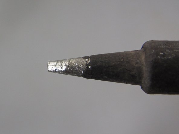
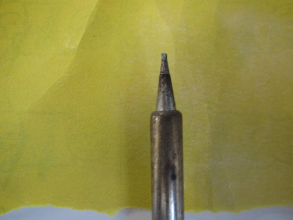
There are two varieties of soldering irons available in the Maker-E. We use conical and chisel tips. Chisel tips are best for general purpose, through hole soldering as they provide the most surface area for heat transfer.
-
This tutorial will follow the example of soldering components for the Bucknell B PCB, but the methods shown here apply in general to all through hole soldering projects.
-
-
-
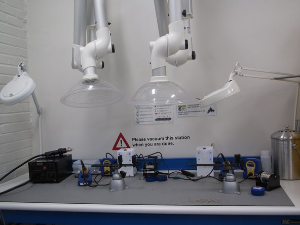
It is best to minimize your exposure to the fumes emitted during soldering. The Maker-E soldering bench is equipped with two adjustable fume hoods which will help to pull away harmful fumes during soldering.
-
The operation of these hoods will be explained momentarily. You should try to solder on this bench when possible.
-
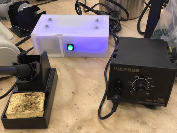
If this bench is not available, you may use the Hakko 936 iron located on the work station in the center.
-
-
-
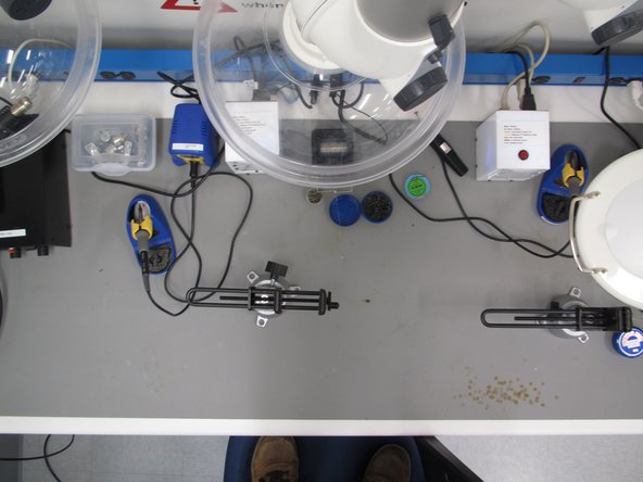
When working in the Maker-E, always solder on a silicone mat. The soldering iron and molten solder can damage the benchtops without the mat in place.
-
Have all of your components ready and know where they will be placed.
-
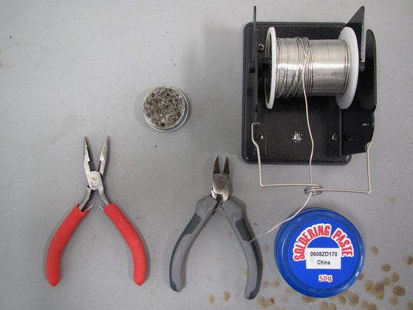
Have any tools you will need on hand, such as wire cutters, vices, “helping hand” tools, flux, solder, tin tinner, etc.
-
-
-
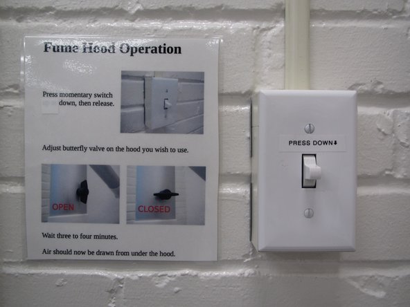
When working in the Maker-E, it is recommended you use the fume hoods available at the soldering bench. Turn on the fume hoods by press down the momentary switch located on the wall to the left of the fume hoods.
-
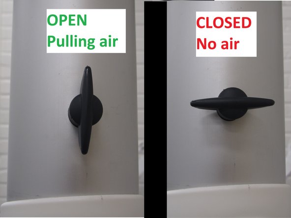
It will take several minutes for the fume hoods to engage. Be patient. While you are waiting, ensure that the butterfly valve for the hood you wish to use is open (parallel to the tube) to pull air. Close the valve (perpendicular to the tube) of the other station to increase airflow to your station.
-
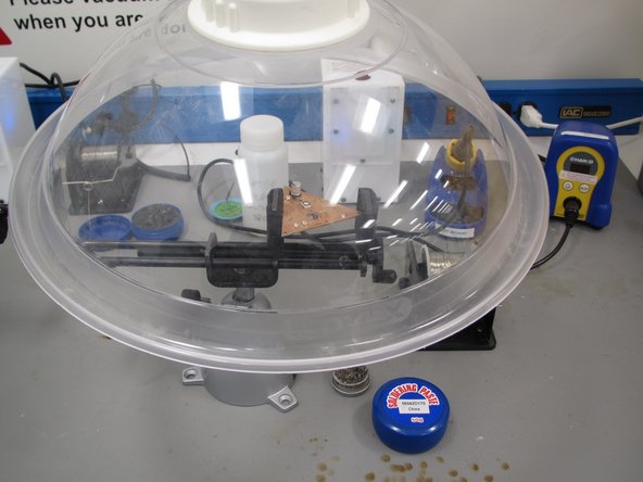
Position the end of the hood with the transparent shield over the top of your work. Get the shield as close as possible without interfering with your work and allowing space for your hands and the iron.
-
-
-
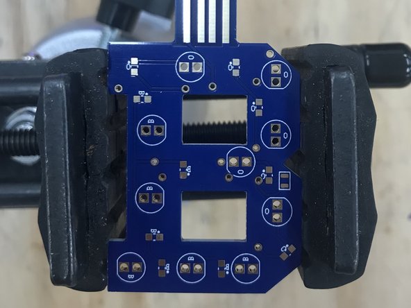
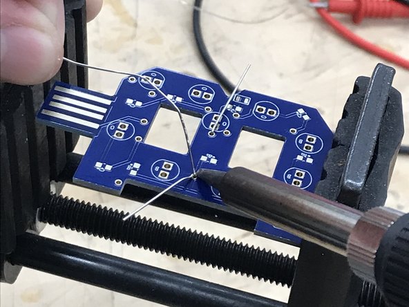
Whenever possible, try to secure your PCB in a vice with a heavy base. This will prevent your board from moving around while you work.
-
-
-
The key to good soldering is proper heat transfer. Solder will never melt if heat does not transfer properly from the tip of the iron to the component(s) being soldered.
-
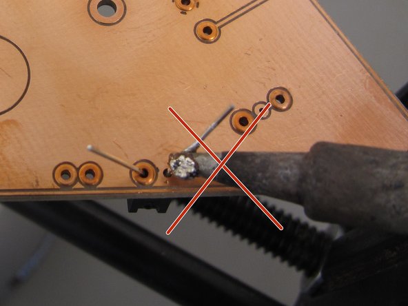
A common misconception is that solder should be transferred as a blob from the tip of the iron to the component being soldered. This is FALSE. Solder is not glue and will never stick to anything that is below the melting point of the solder.
-
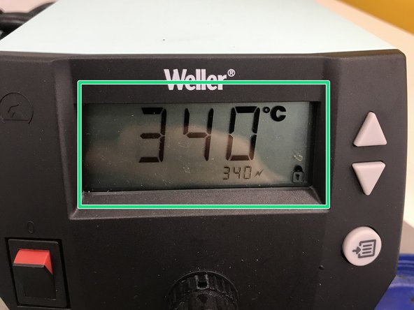
Another common misconception is that you should keep the soldering iron as hot as possible. This is also FALSE. You should keep your iron at or slightly above the melting temperature of the solder you are working with. Increasing the temperature too high will only expedite the oxidation process of the tip, rendering it unusable.
-
You should set your iron tip to 340°C for the Maker-E solder.
-
For the 936 station you should keep the temperature at 700°F.
-
-
-
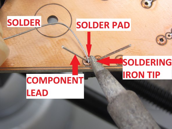
The proper way to solder is to transfer heat from the tip of the soldering iron to the component being soldered, and apply solder to the heated component at the junction between the iron’s tip and the component.
-
-
-
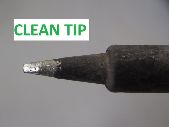
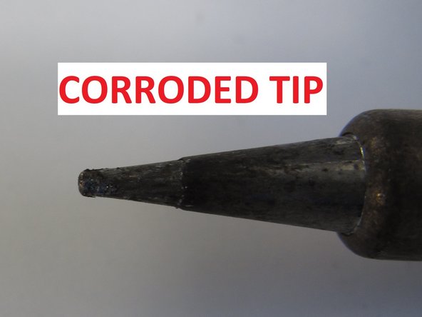
In order for heat to transfer from the iron, the tip must be free of debris and corrosion. You can tell if your iron tip is clean by the color. A dull, grey or black tip is corroded and will not transfer heat properly. A clean tip is silver and shiny and will allow solder to melt and flow properly.
-
-
-
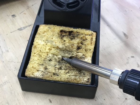
The first step in soldering is to ensure your tip is clean and shiny. Begin by dragging your tip across a wet sponge. DO NOT USE A DRY SPONGE.
-
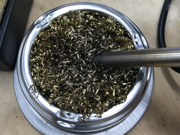
Next, rub the tip of the iron vigorously in the abrasive brass sponge. This will remove any large particles from the iron tip and help to polish it.
-
-
-
The next tool at your disposal is soldering flux. This is a chemical cleaning agent that helps to remove impurities and clean the iron tip and components which will be soldered.
-
Dip the tip of the iron in the flux briefly and then remove. It should hiss and melt while flux is applied.
-
Note that the flux we use is labelled incorrectly as “solder paste.” This is NOT solder paste, but is in fact flux used for cleaning. Solder paste is a completely different item and is used in soldering surface mount components.
-
After applying flux, brush the iron tip in the brass sponge again.
-
-
-
At this point the tip should be relatively clean. To restore a nice shine to the tip and ensure proper solder flow and heat transfer it is a good idea to tin the tip.
-
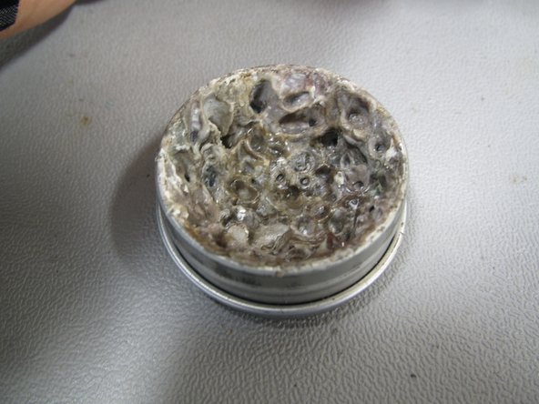
Use the tip tinner available in the Maker-E. This tinner is composed of a mild acid plus some solder which should help remove any oxidation remaining on the tip.
-
Dip the newly cleaned iron tip in the tip tinner. Be sure to cover the entire surface area of the tip. You may need to flip the iron tip over or rotate it while in the tinner.
-
Brush the tip in the brass sponge again to remove excess solder.
-
The iron tip should now be bright and shiny, ready to transfer heat and solder properly.
-
-
-
If all of these steps fail to restore a nice shine to the iron tip, a last resort is to use some fine grit sandpaper to abrasively remove oxidation from the tip.
-
Be sure to do this to a COOL soldering iron tip and brush gently.
-
-
-
The remainder of this tutorial is specific to the the Bucknell B. However, the steps taken to solder components in this particular project will apply to most through hole and surface mount components in other projects.
-
WARNING. Surface Mount soldering MUST be completed first. Through Hole components will melt and possibly start a fire if placed in the oven. Refer to the Pick and place Tutorial for more information: Basic SMD Part Placement
-
-
-
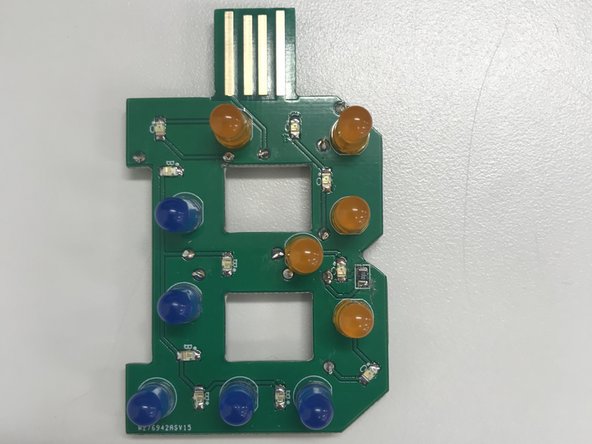
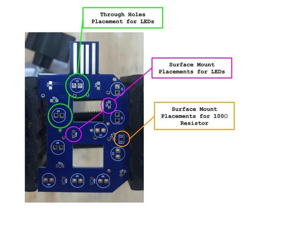
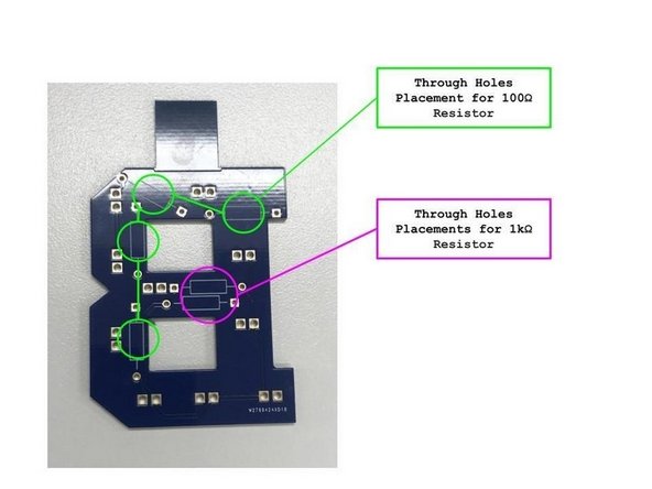
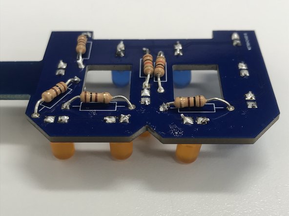
The Bucknell B consists of both TH (through hole) and SM (surface mount) components. It consists of five Orange SM LEDs, five blue SM LEDs, five TH Orange LEDs, five TH Blue LEDs, and one 100Ω SM Resistor.
-
LED resistors should come with the set (these are Through Hole resistors). The Surface Mount resistor can be found in the yellow cart in the Fabrication area.
-
Lay the SMT resistor container flat when opening the small bins! The resistors can all fall out if the container is not flat.
-
-
-
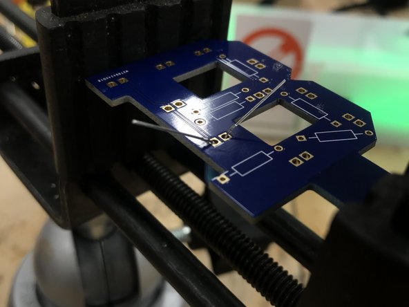
Flip the board over and bend the legs slightly to prevent the component from falling out.
-
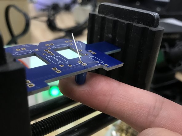
Secure your PCB in a vise. Apply some pressure from underneath to make sure the Resistor/LED is sitting flush with the board. Use caution when doing this with your finger, as heat will travel rapidly from the metal leads you are soldering into the rest of the package. This is more pronounced with completely metal components or packages.
-
Alternatively, you can also use a bit of blue tape to temporarily hold components in place.
-
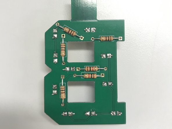
Through Hole resistors should be soldered before Through Hole LEDs. Otherwise, you risk melting the plastic packages of the LEDs when soldering the resistor legs.
-
-
-
Apply a small amount of solder to the tip of a clean iron to whet it and allow solder to flow more freely.
-
Now press the edge of the iron tip to both the component lead and the copper pad surrounding it. The point is to heat up both surfaces which will be joined by solder. If one or both are too cool the solder will not flow properly.
-
Do not be afraid to apply force. Applying a good deal of force ensures proper surface area contact to transfer heat.
-
After applying heat briefly (1 or 2 seconds) you can press the solder wire against the junction where the iron tip touches the component lead and the copper pad. The solder should melt and flow evenly around the lead and onto the surrounding pad.
-
For examples of good versus bad soldering joints, refer to the Digikey's soldering tutorial linked here:https://www.digikey.com/en/maker/project...
-
-
-
When you are done soldering a component in place, be sure to clip the leads flush with the board.
-
You may wish to wear safety glasses when clipping the leads, as the ends of the leads will often fly up when clipped. Alternatively, you can hold the lead with one hand and clip with the other.
-
-
-
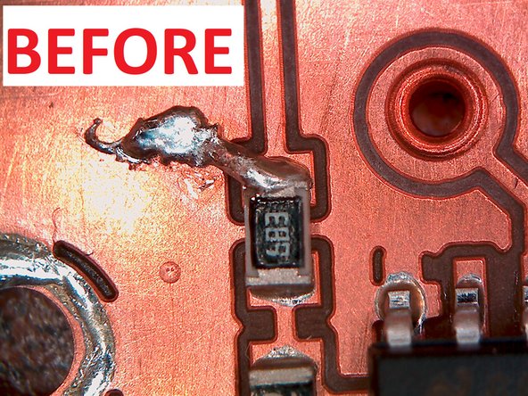
This is a good time to correct any bridges that may have happened during hand soldering or during reflow in the oven.
-
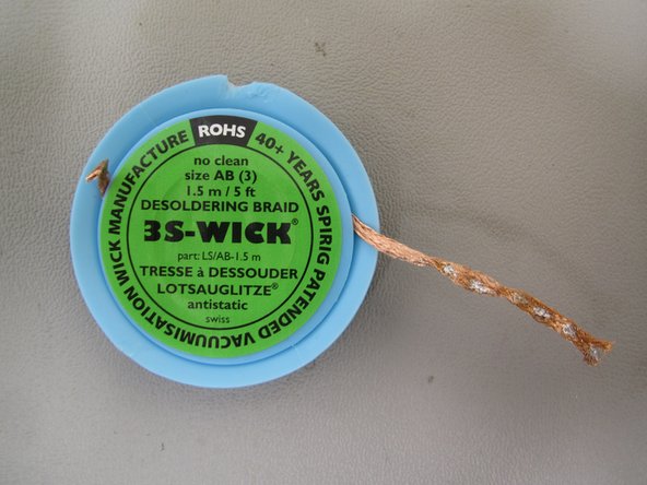
Look for the copper braid or solder wick on the soldering bench. Clip off any used portion of the wick (the section that has solder stuck to it).
-
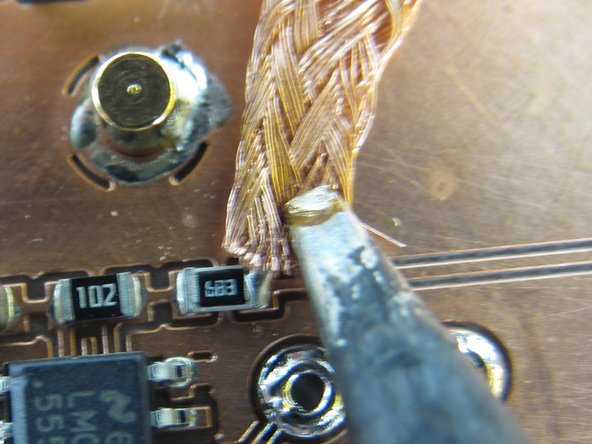
The idea is to sandwich the copper braid between the solder bridge and the iron. The soldering iron will heat up the braid and solder, the solder will melt and wick onto the copper braid, and then the braid can be removed along with the solder bridge.
-
Again, apply a lot of pressure with the iron tip to force the copper braid against the solder bridge. You should be able to see the solder wicking onto the braid.
-
When you lift the iron tip, lift the copper braid along with it. Otherwise you will have soldered the copper braid to your board!
-
The copper braid will conduct heat from the iron back along the length of the braid. Use caution when holding it with your hands.
-
-
-
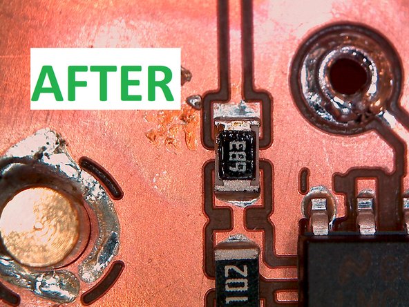
After lifting the iron and the copper braid the solder bridge should be removed. If it is not completely removed you may need to apply more pressure to the braid, or leave the iron on for a longer period of time.
-
-
-
After completing all of the soldering for the Bucknell B (both SMT and through hole) you should add a plastic tab to the bottom of the USB tab.
-
Use a small dab of super glue to hold the tab in place. The glue should set within five minutes. This tab will help ensure the PCB makes good contact inside of a USB port.
-
-
-
Congratulations, you just finished soldering your first PCB!
-


Cancel: I did not complete this guide.
38 other people completed this guide.