-
-
This tutorial explains how to control a NEMA 17 stepper motor using an Arduino, a DRV8825 stepper driver, and a driver module.
-
Required components include a NEMA 17 stepper motor, DRV8825 driver, driver carrier module, Arduino, and a 12 V power supply.
-
This tutorial was created by Jacob Nickle with assistance from Gemini AI and ChatGPT.
-
-
-
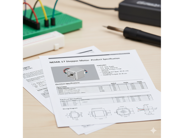
For the purposes of this tutorial, the maximum current rating for the stepper motor should be known.
-
If the stepper motor has an identifying number, look up this information in a data sheet online.
-
If no identifying number is evident, start with a low current limit such as 0.125A and increase until sufficient torque is achieved while ensuring the motor remains cool.
-
A 12 V supply is typically used with NEMA 17 stepper motors, with current limited by the driver as discussed later.
-
-
-
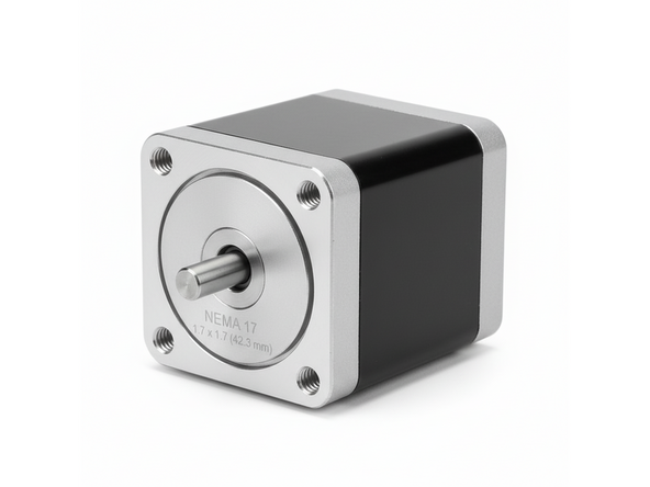
NEMA 17 stepper motors are commonly used in 3D printing, CNC machines, robotics and other applications requiring a balance of size, precision and torque.
-
The rotor is a permanent magnet roughly cylindrical in shape with a shaft extending from the motor housing. It resides in the center of the motor and is the component that rotates.
-
Around the rotor are many coils of wire arranged such that when current is sent through them, the rotor rotates to align with the coils. Providing power to each set of coils in a sequence makes the stepper motor rotate a particular distance producing precise, step-based motion.
-
-
-
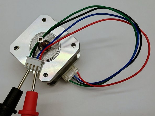
In a NEMA 17 stepper motor there are two independent electromagnetic coils (or windings). Each coil results in two wires which are electrically connected.
-
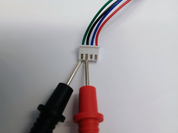
To identify which two wires are electrically connected, use a digital multimeter and measure the resistance between the wires. If the resistance reads between 1 - 50 Ω, those wires belong to the same coil.
-
If no pair of wires measures within this range, the motor coils may be damaged.
-
When connecting to the module later on, note that the 2A/2B pins form a pair, and 1A/1B form the other.
-
-
-
Note that the power supply for the Arduino and for the motor are separate. The Arduino cannot directly power the stepper motor.
-
Finding a power adapter with a barrel jack has the following requirements:
-
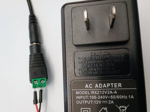
In this tutorial a 12V power adapter will be used. Choosing the correct voltage depends on the stepper driver's rating and safety requirements.
-
The max current of the power adapter must be at or above the stepper motor requirements. 2A or higher is sufficient since the stepper driver itself is unable to handle 1.5A without active cooling.
-
Caution! Verify the polarity of the power adapter using a multimeter before connecting it to the module. Reversed polarity can permanently damage the stepper driver.
-
To connect the power adapter to the module, use a barrel jack to screw terminal adapter as shown in the image.
-
-
-
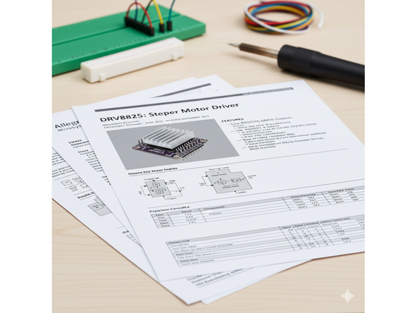
Many stepper motor driver variants are available. DRV8825 will be used in this tutorial.
-
A data sheet link can be found here.
-
There are two ways to identify this driver:
-
First, the onboard chip should have the identifying number of DRV8825.
-
Secondly, the PCB is commonly purple in color.
-
To identify the pins, flip the stepper driver over and notice the markings. The top left pin should be labeled 'DIR' while the top right pin should be labeled 'GND'.
-
Note the pin labeled 'VMOT' (voltage to the stepper motor). This corresponds to the ‘VIN’ pin on the module and determines the stepper driver’s orientation.
-
Ensure correct orientation to prevent damage.
-
-
-
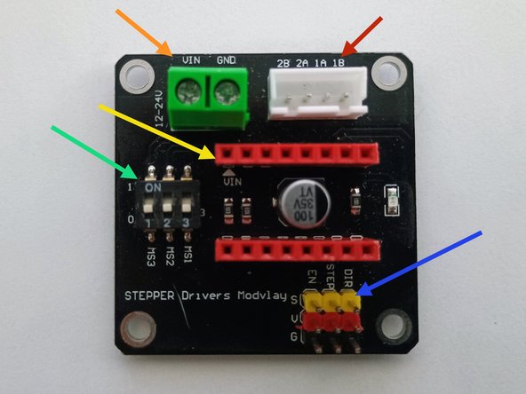
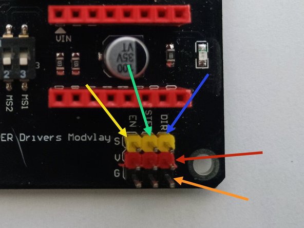
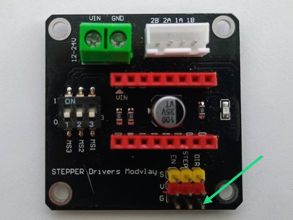
The stepper motor driver module is a simplified interface for controlling a stepper motor with an Arduino. The arrows are color-coded to match the bullet points.
-
The stepper motor is connected here. Note the labeling as discussed previously in step 4.
-
The 'VIN' pin designates the orientation of the stepper motor driver as discussed in step 6.
-
The power supply is connected in these screw terminals. Check and double check positive and negative connections from the power supply and the labels on the module.
-
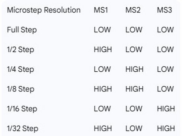
Microstepping can be controlled using the switches. If MS3, MS2, and MS1 are all set LOW "0", the stepper motor will take full steps. For higher stepping resolution (microstepping), refer to the second image.
-
The pins that connect to the Arduino are located in this section of the module.
-
-
-
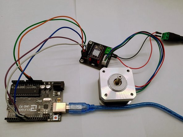
Gather the following components: stepper motor, DRV8825 driver, driver module, 12 V power adapter with barrel connector, Arduino (or equivalent), USB cable, connecting wires, and male-to-female jumpers.
-
Connect the DRV8825 stepper driver into the module in the correct orientation as mentioned previously.
-
Connect the stepper motor to the module with the wires paired correctly as discussed previously.
-
Before connecting the power adapter, insert the wires from the barrel jack into the screw terminals with the correct polarity.
-
-
-
There are various Arduino pin configurations that can work; for clarity, this example uses the following:
-
Connect the 5V pin on the Arduino to any of the 'V' pins on the module.
-
Connect the 'GND' or ground pin on the Arduino onto any of the 'G' pins on the module.
-
Connect pin 7 on the Arduino onto the 'EN' pin on the module.
-
Connect pin 8 on the Arduino onto the 'DIR' pin on the module.
-
Connect pin 9 on the Arduino onto the 'STEP' pin on the module.
-
-
-
Setting the reference voltage is necessary so that the stepper driver or motor does not become damaged.
-
Plug the Arduino into a computer.
-
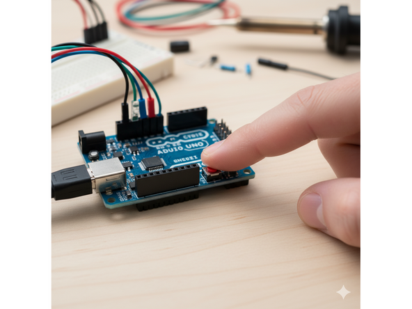
If the wiring is correct, the LED on the module should light up.
-
Press the reset button on the Arduino to clear any previous code.
-
Double-check that the stepper motor is connected to the module.
-
Plug in the power adapter to the barrel jack connector to power the module.
-
Caution: Do not plug in the power adapter unless the Arduino is connected via USB and the stepper motor is connected to the module. Also unplug the power adapter before disconnecting anything else.
-
-
-
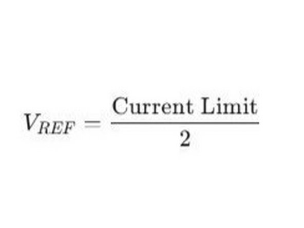
Calculate the reference voltage (Vref) using the following formula:
-
Vref = I / 2
-
I is the current limit of your stepper motor per phase.
-
This equation applies only when the surface mount resistors on the stepper motor driver are 0.1 ohms (R100)
-
For example with a current limit of 0.5A and a R100 resistor, the Vref would be 0.5 (A) / 2 = 0.25 (V)
-
Set Vref to approximately 80% of the calculated value to reduce heat generation.
-
Using the previous example, Vref = 0.25 X 0.8 = 0.2 V
-
-
-
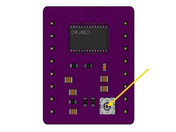
Note the screw on top of the stepper driver as seen in the image.
-
Note the ground pin on the module as seen in the image.
-
Measure the reference voltage by placing the multimeter's ground probe (black) on the module's ground pin and the positive probe (red) on the adjustment screw.
-
Using a non-conductive screwdriver, carefully adjust the potentiometer screw and check the reference voltage again. Do this until the voltage reads about 80% of the calculated reference value.
-
Caution: Be careful not to short components with the multimeter probes.
-
-
-
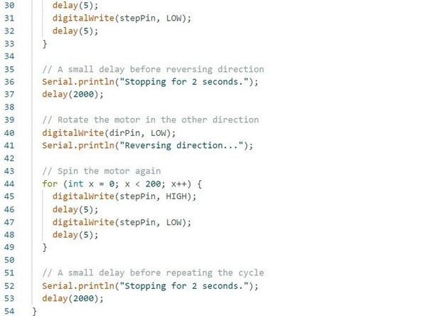
Reference Arduino code can be found in this link.
-
Note also that the code can easily be generated using Gemini AI.
-
Within the prompt mention the module has step, direction and enable pins. Furthermore, mention what type of stepper driver is being used. Specify the desired motor behavior such as direction, number of steps, speed and so forth.
-
Flash the code onto the Arduino.
-
-
-
Movement on the stepper motor should now be apparent.
-
To power off, disconnect the power supply first, then the Arduino.
-
Monitor the temperature of both the stepper motor and driver.
-
-
-
Within the reference code the delay is set to 5 milliseconds. Do not set the value to 0 as a pulse needs to be present for a step to be registered. A delay of 1 ms is typically the fastest reliable speed.
-
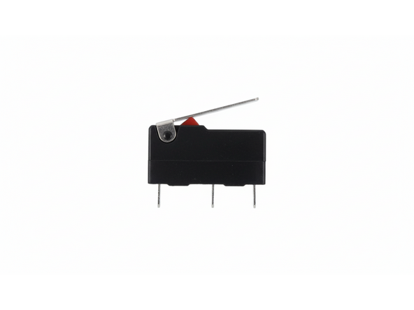
The stepper motor will precisely rotate to the coded position; however, its initial position is undefined. An endstop or mechanical microswitch can be used to initialize position if coded correctly.
-