
Introduction
Tutorial created by Matt Lamparter, with contributions from Margot Vigeant, Alan Cheville, Eric Kennedy, Joe Meiser, Stu Thompson, and Margot Vigeant.
This project is licensed under the Creative Commons Attribution-ShareAlike 4.0 International license.
Video Overview
-
-
(1) Begin with the six sides of the wooden speaker box.
-
Pay attention to the T-slots on the sides, front, and back. These slots need to be on the top of the box when you join the sides to the base.
-
We will use wood glue to join the sides together and a brush to apply the glue.
-
Because we are working with wood glue we suggest using a work surface that is disposable or glue-friendly. In other words, don't do this on the dining room table.
-
-
-
(2) Find a scrap of wood or piece of paper and squeeze out a blob of wood glue. You'll also need a brush.
-
A quick note about the wood glue... be careful not to get it on your clothes. It is difficult to remove. If you get a little on your fingers rub them together for a bit and it will flake off. For larger amounts, we suggest taking it off with a rag/towel.
-
Starting with the bottom piece of the box, brush wood glue onto the interior of the teeth of one of the long sides. The bottom piece is identified by the absence of holes or T-slots.
-
Now repeat this process for the back piece of the box. The back piece is identified by the two small holes cut out in the bottom left corner.
-
Finally, join the back to the bottom. Be sure to have the two small holes in the back oriented at the bottom left. Hold the pieces together for a minute to let the glue set up.
-
-
-
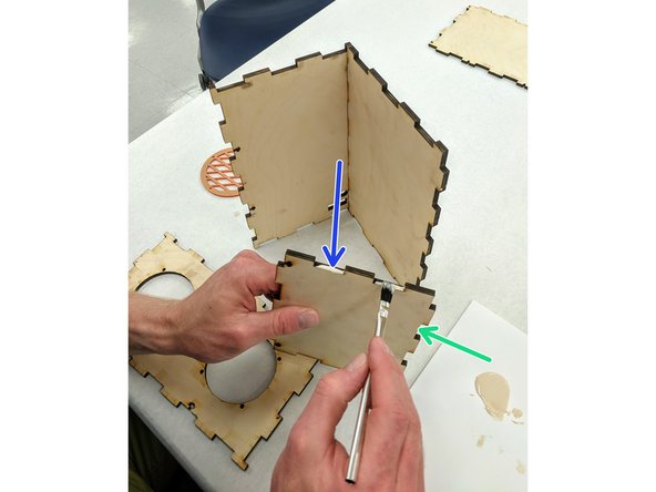
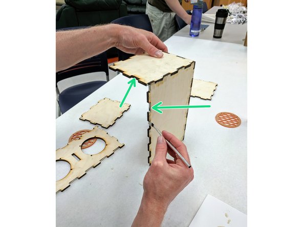
(3) Locate one of the two small sides of the box. The two sides are identical.
-
Paint the inside of the teeth on the bottom (longer) edge of the side piece. Note that the T-slots should be on top, opposite the glue side.
-
Also paint the inside of the teeth on one side of the side piece.
-
With your bottom/back assembly standing vertically, join the side piece to the assembly.
-
Again, be sure that your T-slots are at the top of the box.
-
-
-
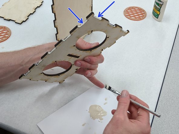
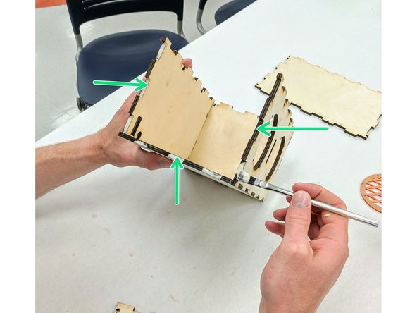
(4)Locate the front of the box, the piece with the large circular holes. Apply glue to the inside of the teeth along the bottom edge (opposite the T-slots) and to the inside of the teeth along one of the two short sides.
-
Apply glue to the box assembly along the edges where the front will mate: the teeth along the front of the bottom piece and the teeth along the front of the side piece.
-
Join the front to the rest of the box assembly. Be sure to line up all of the glued edges.
-
Again, ensure that the T-slots of all three pieces are at the top of the box.
-
-
-
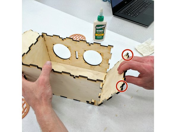
(5)Orient the box so that the open side is facing you. Apply glue to the inside of the teeth on the bottom and two side edges.
-
Apply glue to the inside of the teeth along the mating edges on the remaining side piece. Beginning at the bottom and then rotating upward, join the final side to the box.
-
As with the other pieces, ensure that the T-slots face the top of the box.
-
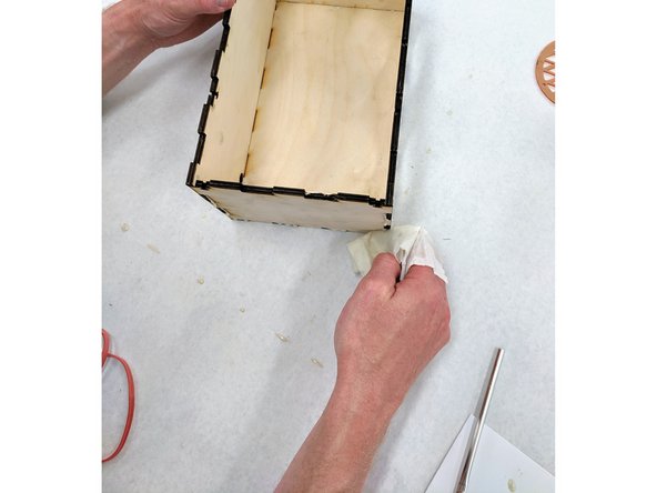
Once you have these five pieces of the box glued together, take a piece of paper towel and wipe off any excess glue that may have oozed out of the joints.
-
-
-
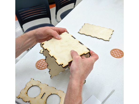
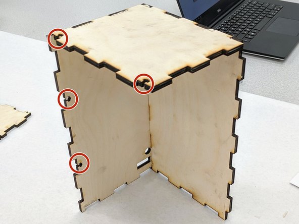
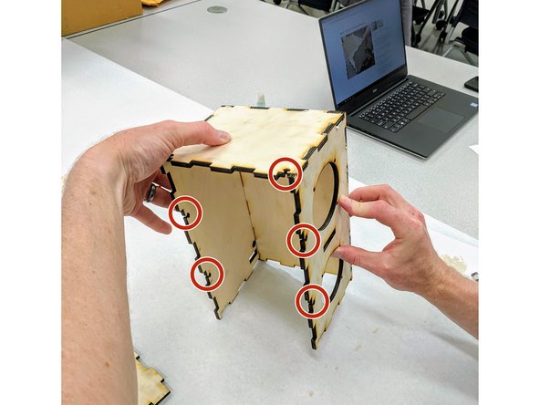
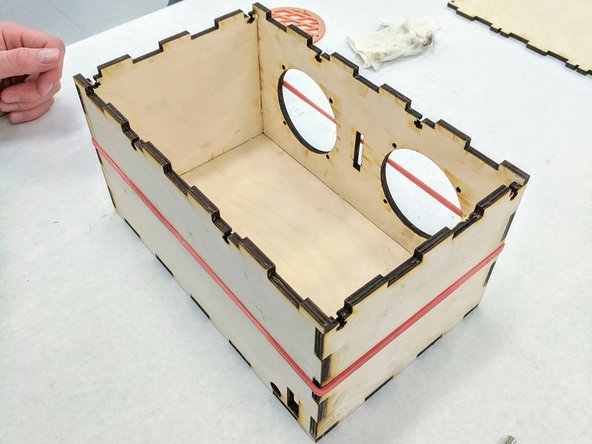
(6)Wrap a large red rubber band around your box. This will apply pressure to all four sides and hold them together while the glue sets up.
-
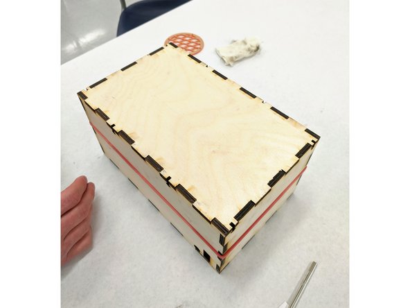
It helps to set the top of the box in place while the glue sets. This reinforces the joints and prevents the walls of the box from bending too far inward.
-
Set your box aside so the glue has time to dry. While the glue dries you will solder wires to the speakers.
-
-
-
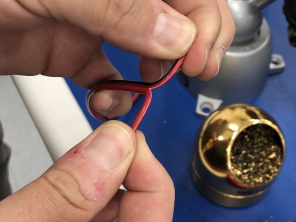
(7)There are three lengths of red and black 18 gauge wire in you bag: one 12" and two 18" lengths. Locate one of the 18" lengths.
-
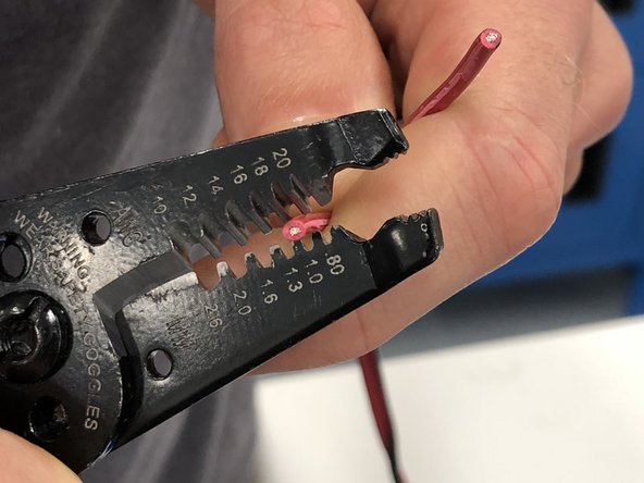
Using your fingers or a pair of wire cutters, separate the red and black wires about three inches.
-
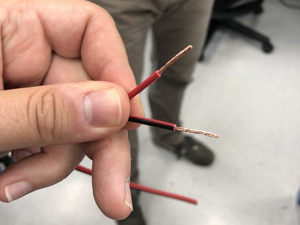
Now use wire strippers to remove about 3/8" of insulation from the end of each of the two wires.
-
Twist the stranded copper wire into a uniform bundle for both red and black wires to keep things tidy.
-
Repeat this step for the other end of your length of 18" wire. Then repeat the entire process for the second length of 18" wire as well as for the 12" length.
-
-
-
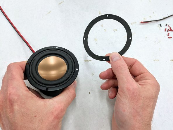
(8)Remove one of the speakers from the white cardboard box and locate the included rubber gasket.
-
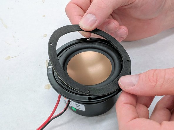
Remove the paper covering from the back of the gasket and adhere the gasket to the front of the speaker. Do not place the gasket on the back of the speaker.
-
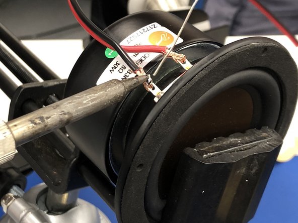
Gently place your speaker in a vice. Locate the two metal tabs near the front of the cone of the speaker.
-
Insert the red wire from one of the 18" lengths through one of the two metal tabs and wrap the wire back to make a firm connection. Repeat this with the black wire in the other tab.
-
Apply heat with the broad edge of a hot, clean soldering iron simultaneously to both the metal tab and the copper wire. After a second or two apply solder to the hot junction.
-
If the wire and speaker tab are hot enough the solder will flow onto both and form a solid bond. Remove the solder and then the soldering iron. Repeat this process for both wires. Then repeat this entire step for the second speaker.
-
-
-
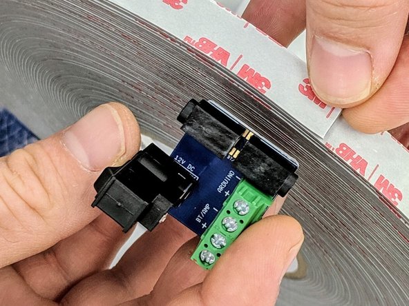
(9)The wood glue should now be sufficiently dry to continue work. Remove the lid. In your bag, locate the small blue printed circuit board (PCB) with the barrel jack/rocker switch and green terminal blocks.
-
Flip the PCB over so the soldered leads on the bottom are visible. If leads are long and sticking up from the PCB more than about 1/8" use a pair of flush cutters to trim these down nearly flush with the PCB.
-
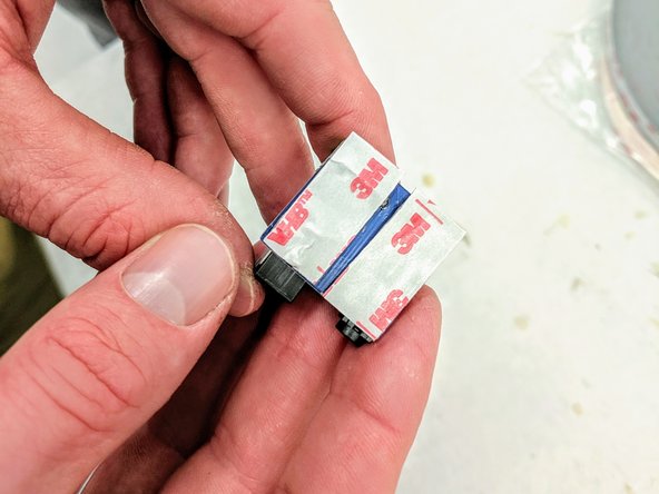
Locate the wider of the two VHB tapes. Cut two strips of length equal to the width of the PCB. Apply these strips to the bottom of the PCB.
-
-
-
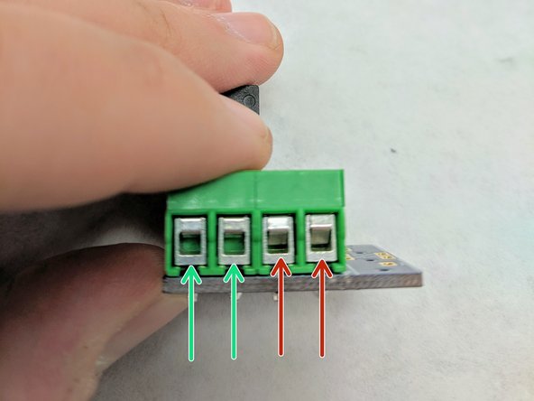
(10)Look at the front (square holes) of the green terminal blocks and ensure that the blocks are open. In the picture, the left blocks are open and the right blocks are not.
-
If the blocks are closed (shown in the right two blocks here), use a small screw driver to rotate the corresponding screw counterclockwise and open the block.
-
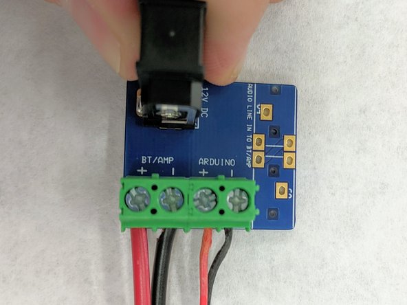
Find the remaining 12" length of 18 gauge wire. Insert one of the red ends into the far left terminal block labelled "+ BT/AMP". Insert the black lead into the "-- BT/AMP" slot. Tighten the screws of these terminal blocks to hold the wires in place.
-
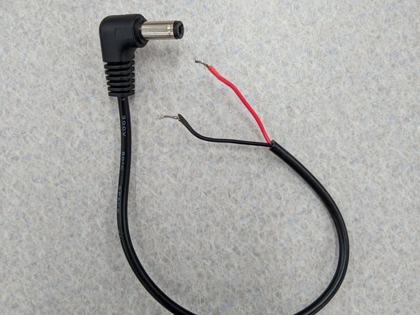
Locate the right angle barrel plug in your bag. The other end of this plug has exposed leads. Insert the red lead into the terminal block labelled "+ ARDUINO" and the black lead into the "-- ARDUINO" slot. Tighten the screws to secure the leads.
-
-
-
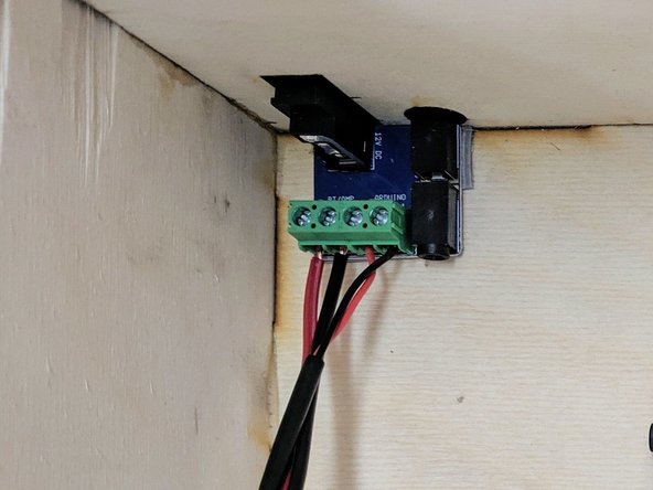
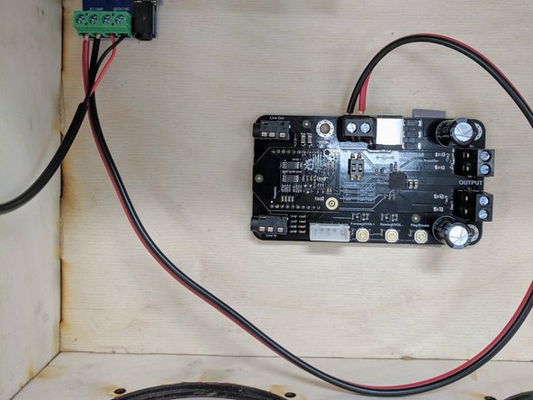
(11)Remove the white backing material (the "3M" side) from the VHB tape and adhere the PCB to the bottom left corner in the rear of the box. Be sure to align the barrel jack/rocker switch and audio jack with the cutouts in the rear of the box.
-
Apply firm, downward pressure to ensure that the VHB tape makes good contact with both the PCB and the wooden base.
-
The VHB tape will take awhile to set so don't wiggle the PCB for awhile.
-
-
-
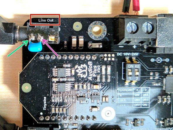
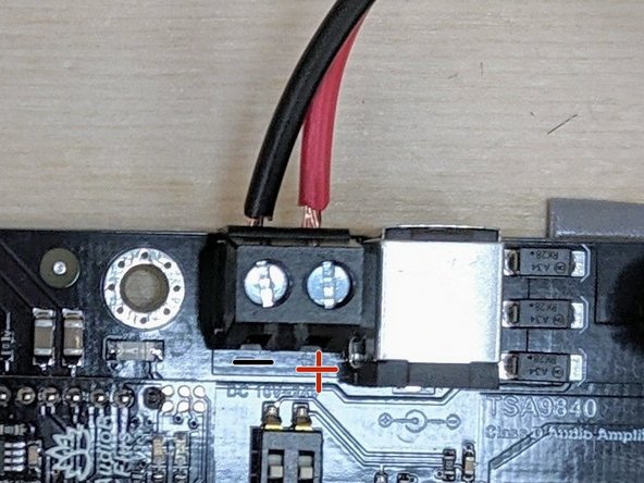
(12)In order to mitigate some issues with electrical noise on the audio signal going from the BT/amplifier PCB to the Arduino we have soldered a small capacitor across the line out jack. If you are participating in BFab this step has already been taken care of for you. You may skip this step.
-
If you are completing this guide outside of BFab you may want to add this capacitor yourself. The exact value is not that important, just something large enough to attenuate noise. We used a value of 0.68 uF.
-
Solder one lead of the capacitor to the sleeve (ground) connection of the jack.
-
Solder the other capacitor lead to the tip or ring connection of the jack. In our example we have soldered to the ring connection.
-
-
-
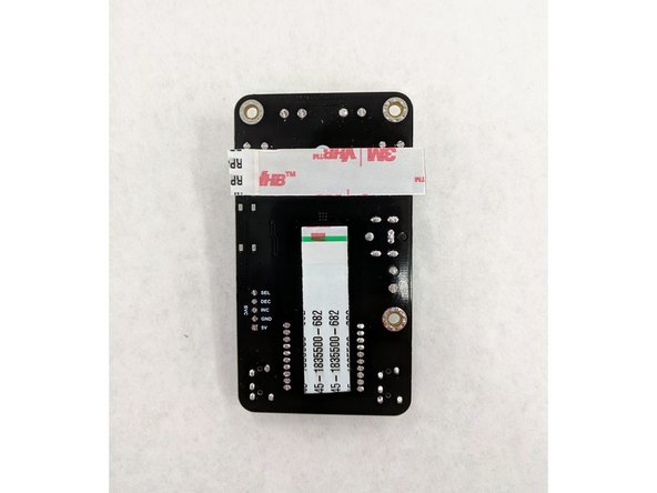
(13)In your bag, locate the black cardboard box which contains the bluetooth/amplifier PCB and remove the PCB from the box.
-
Flip the PCB over and clip any leads that protrude from the back of the PCB more than an 1/8" using flush cutters.
-
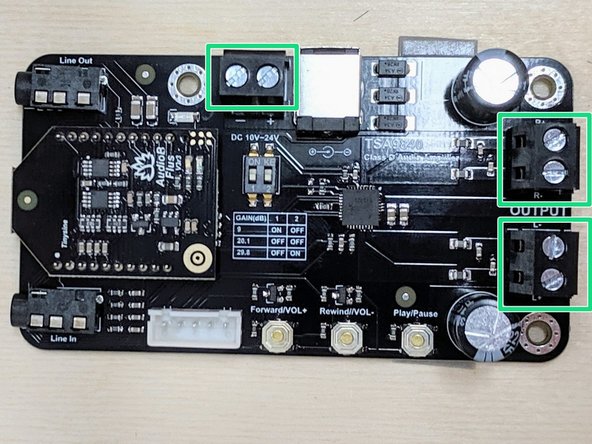
Ensure all of the 6 terminals on the board are open. Use a screwdriver to open them if they are closed. Wires will be connected to each terminal.
-
Again, use the wide VHB tape to form a T shape on the back of the PCB.
-
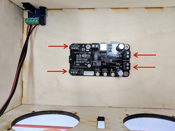
Remove the white strips from the tape and position the PCB in the center of the bottom of the box. Rotate the PCB so that the 1/8" audio jacks are on the left and the two terminal blocks are on the right.
-
-
-
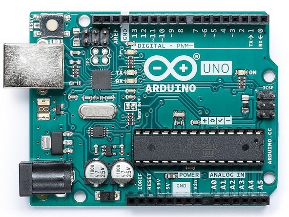
(14)Locate the Arduino board in your bag and remove it from the box.
-
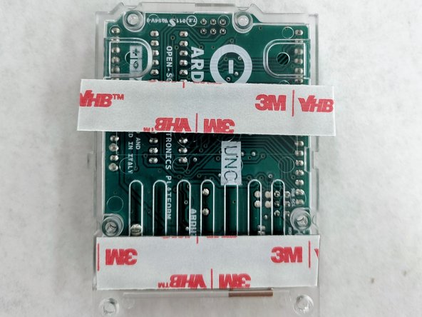
Apply two strips of the wide VHB tape to the back plastic sled which houses the Arduino.
-
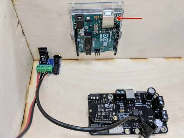
Remove the white strip from the VHB tape and adhere the Arduino inside the box on the back panel as shown here. Orient the board so the USB port is pointing up, so it can easily be connected to and programmed.
-
-
-
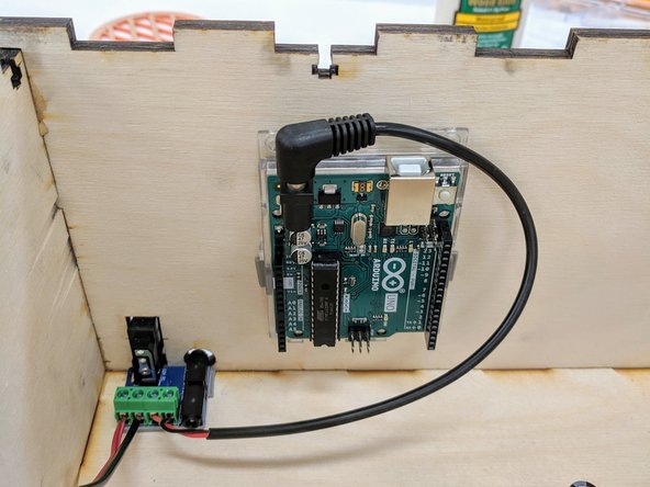
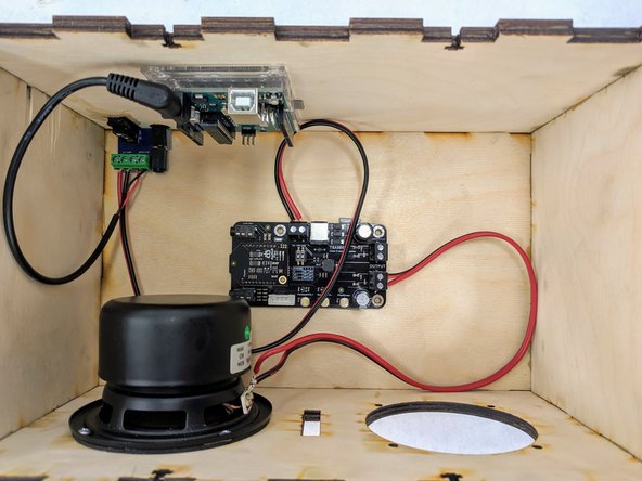
(15)Begin by plugging the barrel plug into the Arduino's barrel jack on the left side.
-
Now connect the 12" length of black and red wire to the terminal block on the BT/amplifier board. Use a screwdriver to close the terminal blocks on the wires.
-
Observe polarity when inserting the wires: red in the + side, black in the -- side.
-
Give the wires a gentle tug to make sure they are securely held in place.
-
-
-
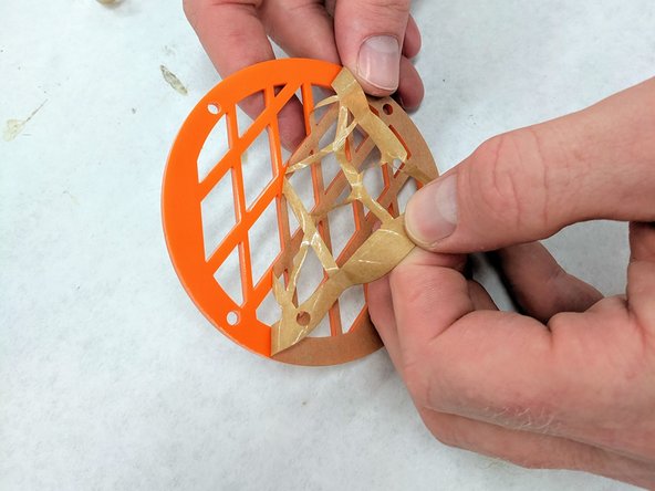
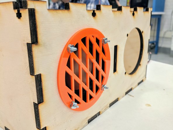
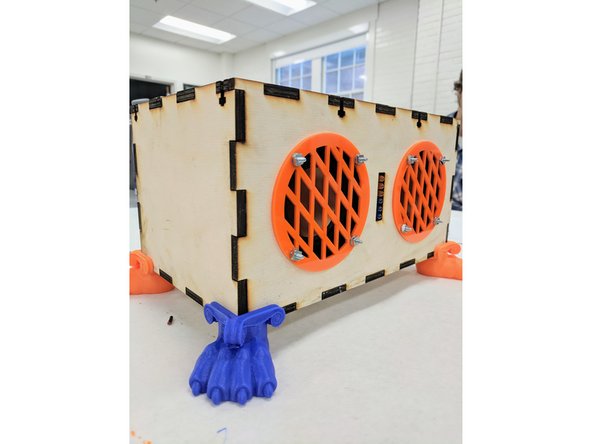
(16)Choose two laser cut, acrylic grilles from the supply provided. Remove the protective paper from both sides of the grilles.
-
Select eight 4-40 3/4" philips screws, eight washers, and eight nuts from the supplies provided. You will use four of each to fasten each speaker to the front panel of the box.
-
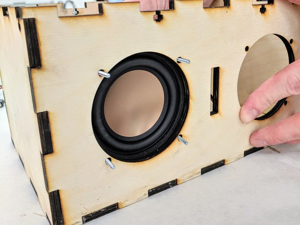
Place one speaker INSIDE the box on the left side. Rotate the speaker so that the four mounting holes align with the holes in the panel and so that the wires soldered to the speaker are on the right side. Press the rubber gasket flush against the front panel.
-
OPTION - you may either Insert four screws from inside the box through the four speaker mounting holes OR insert them from the outside, using washers to space the nuts against the speaker. The choice is aesthetics vs. difficulty in manipulating the nuts/bolts. Your call!
-
Slide the grille over the speaker cutout, aligning the screws with the holes in the grille. Place a washer over the screw, then thread a nut onto each screw. Tighten all.
-
We will add the right speaker after wiring up the left.
-
Finally, marvel at your awesomeness. It is starting to look good.
-
-
-
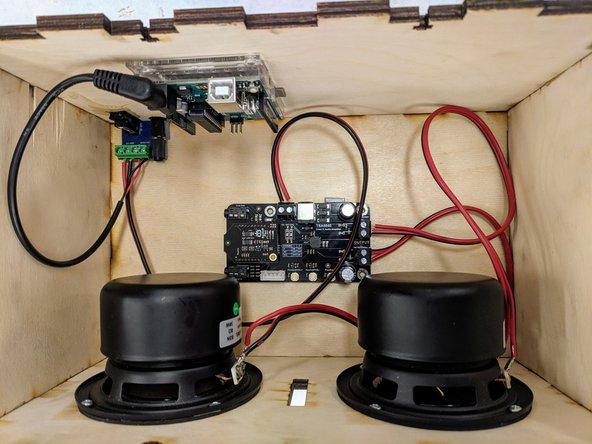
(17)Attach the wires from the left speaker to the "Output L" terminal block on the BT/amplifier PCB. This terminal block is closer to the front of the speaker box.
-
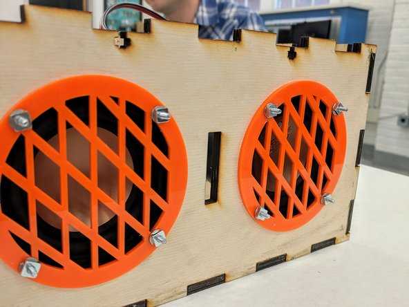
Repeat the last step to fasten the right speaker and grille to the box. You will use the remaining four screws, washers, and nuts.
-
Attach the wires from the right speaker to the "Output R" terminal block on the BT/amplifier PCB. This terminal block is closer to the back of the speaker box.
-
-
-
(18) NOTE - If you are working on this on your own, follow the steps below now to solder your VU meter PCB. If you are working on this in the B-Fab workshop, you will do that in the "soldering" workshop. You should now skip to step 28.
-
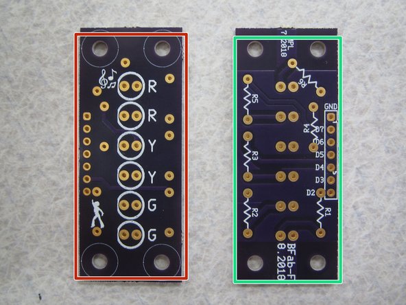
Locate your VU meter PCB. Notice that it has a:
-
FRONT
-
BACK
-
You will be attaching six LEDs. Insert the LEDs from the front so that the plastic case sits on top of the white circle and the legs or leads stick out the back of the PCB.
-
Read the next few steps for some information about LEDs and how to solder.
-
-
-
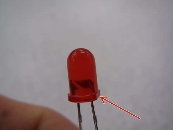
(19) Diodes are polarized devices with an anode and cathode. This means that when you solder them in place you must pay attention to how you orient them. If they are attached backwards, they will not work.
-
In order to determine how to properly orient the LED, look at the plastic case. One side will have a small, flat edge.
-
Be sure to line up this flat edge with the flat edge on the silkscreen layer on the top side of the PCB.
-
-
-
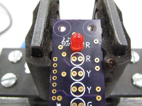
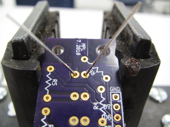
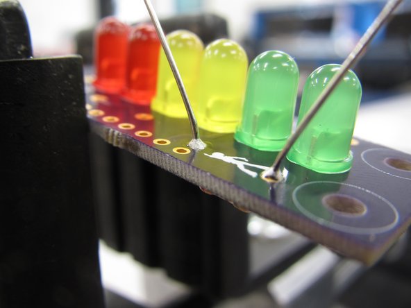
(20) It is best to clamp the PCB in a vice to provide a sturdy base against which you can apply adequate pressure while soldering.
-
The vice also allows you to push up on the plastic case of the LED to keep it flush while soldering in place.
-
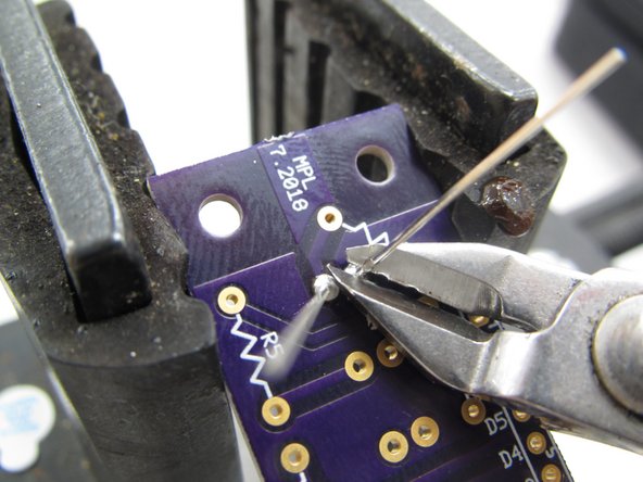
When you have successfully soldered both leads be sure to clip them flush with the PCB.
-
In Pennsylvania we are required to point out that good solder joints look a little like Hershey Kisses.
-
-
-
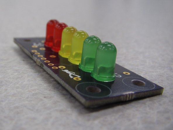
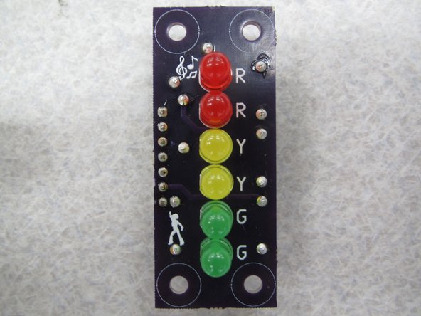
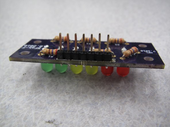
(21) Solder the LEDs one at a time. When you are finished your PCB should look like the example shown here. (LED colors may vary.)
-
-
-
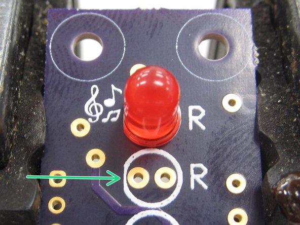
(22) Next you will solder the resistors on your PCB. Resistors are not polarized so their orientation does not matter.
-
Be careful! While the LEDs were in a plastic case which could be held by hand during soldering, the ceramic resistor case WILL GET HOT during soldering. Do not touch the resistor while soldering!
-
Each LED has its own current limiting resistor. All six resistors are of the same value, so it does not matter how they are paired with the LEDs.
-
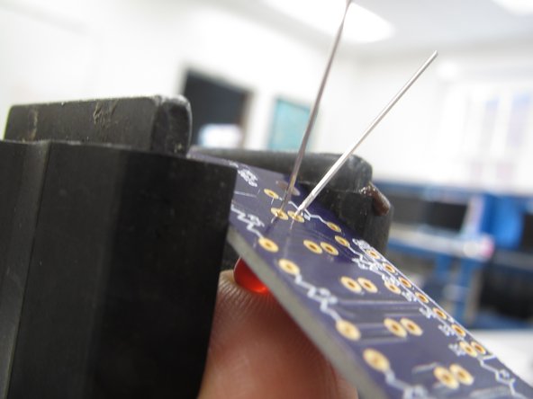
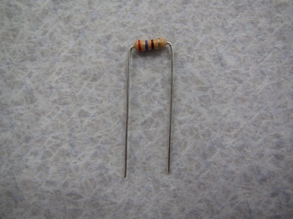
Choose a resistor and begin by bending its two leads down at a 90 degree angle flush against the ceramic body.
-
Next insert the resistors from the bottom of the PCB so that the leads stick up from the top of the board. Note that this is opposite the insertion of the LEDs. DO NOT SOLDER THE RESISTORS ON THE SAME SIDE AS THE LEDS OR YOUR PCB WILL NOT FIT PROPERLY IN YOUR SPEAKER ENCLOSURE.
-
-
-
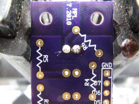
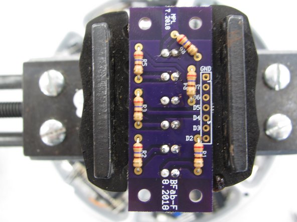
(23) While the resistors are not polarized and their orientation does not matter from a functional standpoint, it is still best practice to keep them all oriented in the same direction.
-
Keeping components of a similar type oriented in the same direction aids in any potential troubleshooting. With components in the same direction it is easier to read markings or other indicators on the component packages.
-
The completed example shown here has all of the resistors oriented in the same vertical direction (note the stripe color pattern), with the top right resistor rotated slightly counter clockwise.
-
-
-
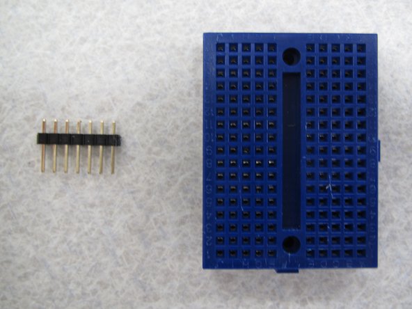
(24) The final component to be soldered is the 7-pin strip of header pins.
-
While it is possible to solder these without any special techniques it can be helpful to use a breadboard to keep the pins straight and flush with the PCB.
-
A breadboard will also provide a flat, rigid surface against which to solder. It also prevents you from having to use your hands to hold the pins in place and potentially burning yourself. Ouch!
-
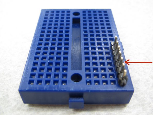
Begin by inserting the long end of the header pins into the breadboard. Be sure to place the pins on the edge of the breadboard and not in the middle.
-
-
-
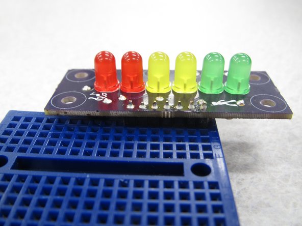
(25) With your header pins securely inserted in the breadboard place your PCB on top of the pins.
-
Be sure to have the LEDs facing upright when you lay the PCB on top of the header pins.
-
Solder the seven pins in place and then remove the completed PCB from the breadboard.
-
-
-
(26) Your completed PCB should look like the example shown here. Note:
-
LEDs are all on the top side of the PCB while resistors and header pins are on the back of the PCB.
-
LEDs are all properly oriented with their flat edges all facing the left edge of the PCB
-
All components are sitting flush with the PCB
-
Solder joints/leads are clipped flush with the PCB
-
Header pins are pointing straight down from the bottom of the PCB
-
-
-
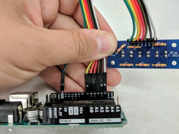
(27) Remove the Arduino from the plastic sled. Locate the 7-wire ribbon cable in your bag. Your ribbon cable colors may not match those shown here.
-
Insert one of the end wires of the ribbon cable into the GND slot along the edge of the Arduino closest to the USB connector.
-
Insert the remaining six wires, sequentially, in the Arduino ports labelled 7, 6, 5, 4, 3, 2.
-
Attach the other end of the ribbon cable to the back of your LED VU meter PCB where the header pins protrude. Pay attention to the labels on the PCB and match the wires correctly between the Arduino and LED PCB.
-
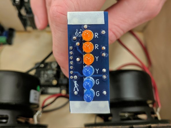
Place two strips of the narrow VHB tape along the top and bottom of the FRONT of the LED PCB.
-
Remove the white strips from the VHB tape and firmly press the LED PCB against the inside of the front panel to adhere it to the speaker box. Ensure that the LEDs fit inside the slot in the front panel (pointing out) and that the PCB is rotated such that the ribbon cable is closest to the left speaker.
-
-
-
(28) NOTE - this is where the B-Fab folks should skip to if they're not in the soldering session! Welcome back, friends!
-
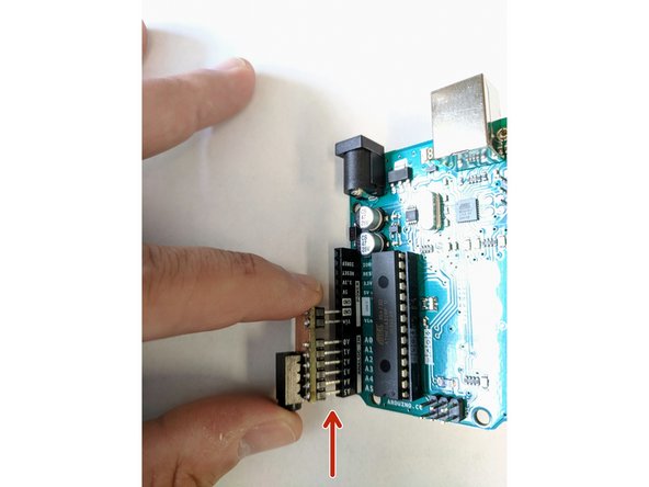
Locate the small analog audio-in PCB in your bag and insert it in the bottom left side of the Arduino from pin A5 to GND.
-
Place the Arduino back in the plastic sled.
-
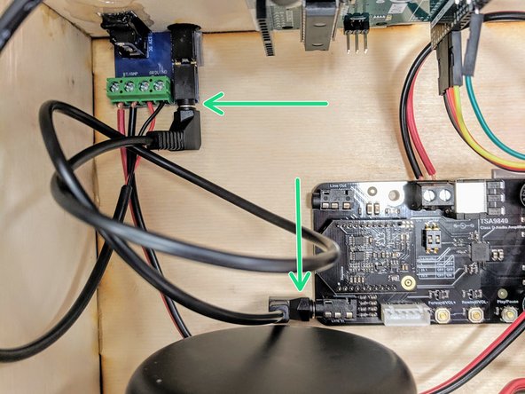
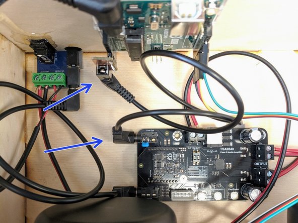
Locate one of the two 3.5 mm stereo audio cables in your bag. Insert one end into the jack on the powerin/line in PCB. Insert the other end into the "Line In" jack on the BT/amplifier PCB. This jack is closer to the speakers.
-
Use the second 3.5 mm stereo audio cable in your bag to go between the "Line Out" jack on the BT/amplifier PCB and the Arduino analog-in PCB jack.
-
In short you are connecting the exterior audio jack on the box to the "line in" on the BT board and the "line out" of the BT board to the Arduino.
-
-
-
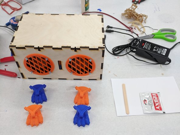
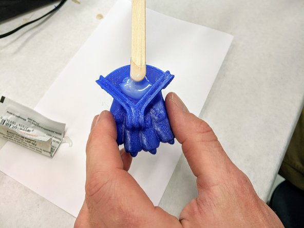
(29) Choose four 3D printed feet from the supply provided. Use whimsy or reserved caution at your discretion when choosing feet.
-
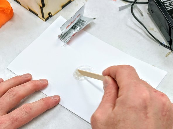
Pick up a packet of epoxy from the supply provided. You will also need a popsicle stick and an index card.
-
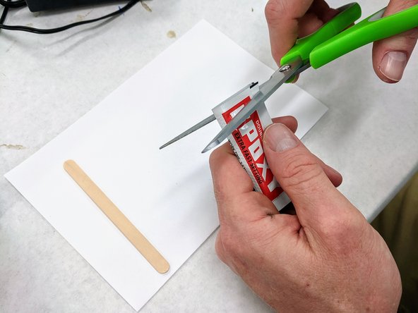
Cut the top off of the epoxy packet. Squeeze the contents of both sections onto the index card. Use the popsicle stick to completely mix the two parts of the epoxy until it turns somewhat white.
-
-
-
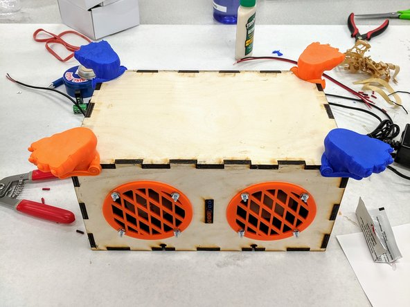
(30)Flip your speaker box over so that the bottom is facing up.
-
Using the popsicle stick, apply some of the epoxy to the mounting point of one of the feet.
-
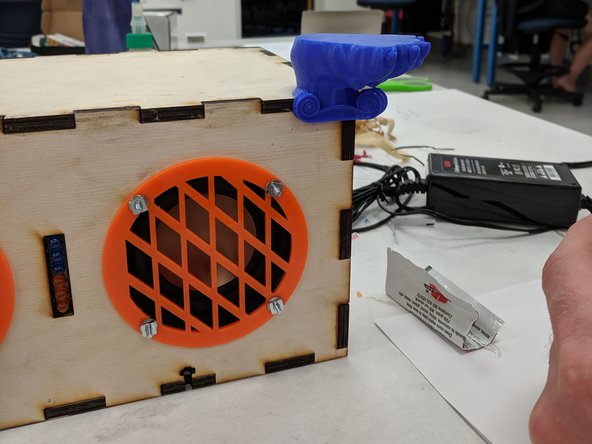
Place the foot on one of the four corners of the box. Hold it in place for a minute to allow the epoxy time to begin to cure.
-
Repeat this step three more times for the remaining feet.
-
-
-
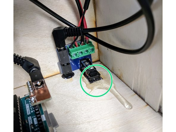
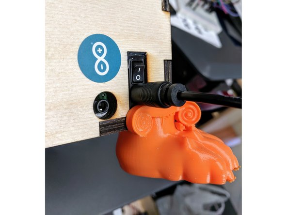
(31) While you have the epoxy handy, we found it was helpful to shore up the power switch with a dab of epoxy to adhere the switch module to the box.
-
Be careful NOT TO EPOXY the switch itself or you'll have a darn hard time turning it off and on.
-
There's no perfect way to do this. We ended up with an unsightly blob. Fortunately it is on the inside of the box.
-
-
-
(32) NOTE - if you're at B-Fab, lightly set the top of your lid on your speaker now, do not yet attach the lid. You'll need the lid for the laser cutting workshop, and you'll need to remove the lid for soldering/ Arduino. But do go ahead and collect the nuts/screws as described below now and come back to this step before leaving.
-
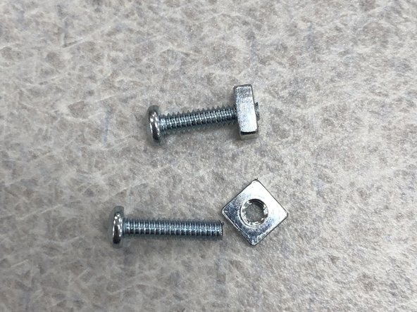
(31) Select eight 4-40 1/2" screws and eight nuts from the supply provided.
-
Pre-thread the nuts onto the eight screws.
-
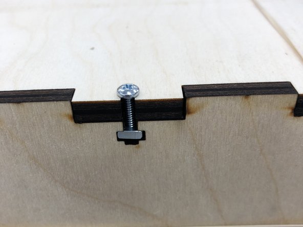
Place the lid back on your box.
-
Place nut-and-screw assemblies into each of the eight T-slots in your box and finger-tighten.
-
-
-
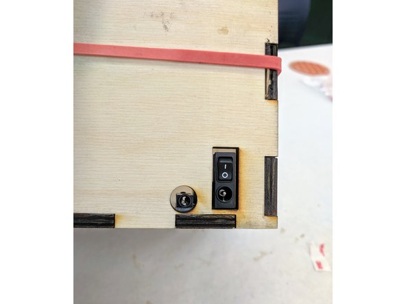
(33) Find the 12V DC power supply in your bag and connect it to your speaker box via the barrel jack in the back panel. Plug the other end into a wall receptacle.
-
Flip the rocker switch, located above the power barrel jack, to the up position. You should hear a chime.
-
Using a bluetooth enabled device, connect to your new speaker box -- add a new Bluetooth device. The box should show up as TSA9840 on your smartphone.
-
Rock out!
-
Note: we can't all turn on our speakers for the first time at once, or you'll probably pair with the wrong speaker because all of them appear as TSA9840. No, we haven't figured out a way to change this. Sorry.
-
-
-
This project is licensed under the Creative Commons Attribution-ShareAlike 4.0 International license.
-


Cancel: I did not complete this guide.
One other person completed this guide.