
Introduction
Tutorial Published by Margot Vigeant, with contributions from Eric Kennedy, Matt Lamparter, Joe Meiser, Stu Thompson, and Margot Vigeant.
Video Overview
Featured Document
-
-
Start with one of each piece from the laser file (see attachment) and two matched pairs of 3-D printed feet (see attachment). You will also need 8 3/4" 4-40 screws.
-
-
-
Using a philips head screwdriver, open the holes in the tops of the feet slightly.
-
Using two 4-40 3/4" screws, attach each of the four feet in the bottom panel. Use a drill to attach the feet most of the way, then hand-tighten until snug.
-
Note that the feet are directional, so make sure they are facing the way you would like to see them.
-
-
-
You will need wood glue at this point. Find a scrap of wood of piece of paper and squeeze out a 1.5" or so blob. You'll also need a brush.
-
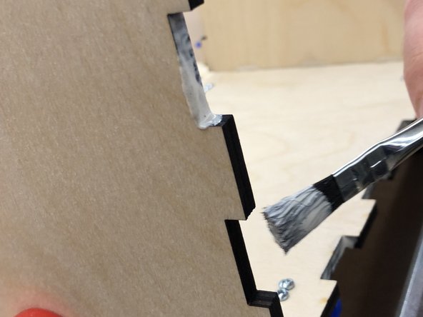
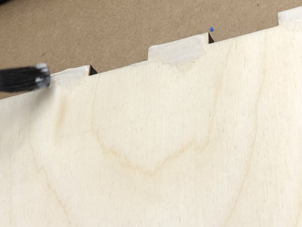
Starting with the bottom, paint wood glue onto the interior of the teeth of one of the short ends of the box.
-
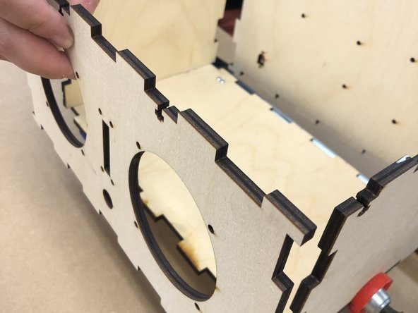
Take one of your short side pieces. The top always has the "keyhole" cut out. Select which side you want to face outwards. On the other side, paint wood glue onto the ends of the bottom teeth.
-
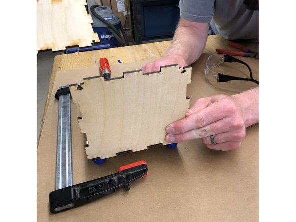
Affix the short end in place. Get a partner to hold it while you repeat this process with the other short end.
-
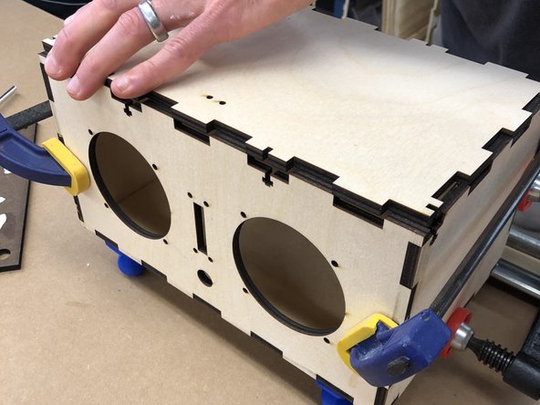
Clamp the short ends onto the box near the bottom as shown.
-
-
-
The back and front of the box have keyholes in the top.
-
The rear wall of the speaker must have the hole for the power jack in the lower left-hand corner, as you face the front of the box. That is, there is only one way that this segment can face.
-
The front wall of the speaker can go with either side facing outward, as long as the keyholes are at the top.
-
Paint wood glue inside the teeth on the back-sides and the bottom of the box.
-
Paint wood glue on the bottoms of the teeth on the bottom and sides of the back panel.
-
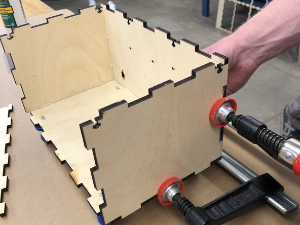
Affix the panel in place. Get a partner to hold it while you repeat the process with the front. Clamp in place or wrap rubber bands around the speaker to hold it in place.
-
-
-
Place DO NOT GLUE the top of the box on the top of the box. This helps ensure the other pieces maintain the correct spacing.
-
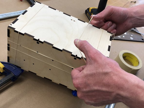
If you have used clamps, remove them. Rubber band the box along all axes, using at one or two rubber bands per direction.
-
Allow the glue to set while you move on to soldering. Wood glue does not fully set for several hours, so be gentle with your box and keep the rubber bands on for added support.
-
-
-
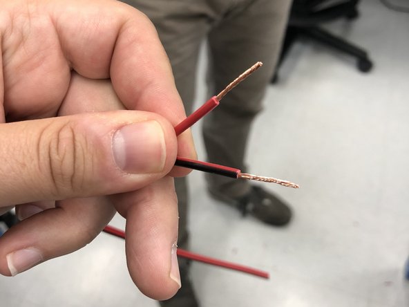
Start with about 5' of 18 gauge wire. Cut into five 1' segments.
-
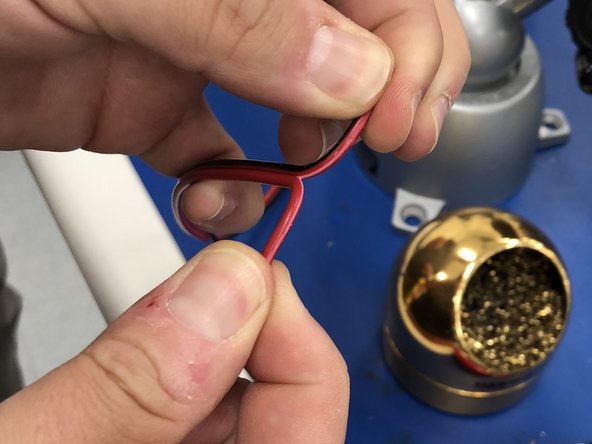
Take four of the segments and separate the two wires for about 2". Completely separate the last segment into two wires. You will only be working with the red side of this wire.
-
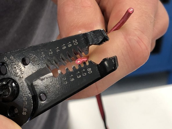
For two of the 1' wires, strip the split wires 1" at one end only.
-
For all remaining wire ends, strip the ends 3/8".
-
Twist the exposed wire strands to ensure they all stay together for each of the exposed ends.
-
-
-
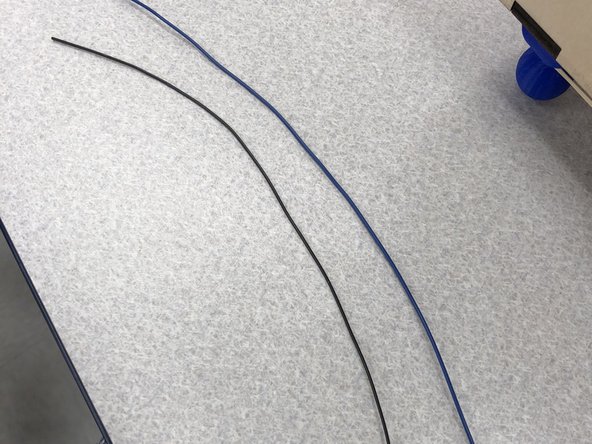
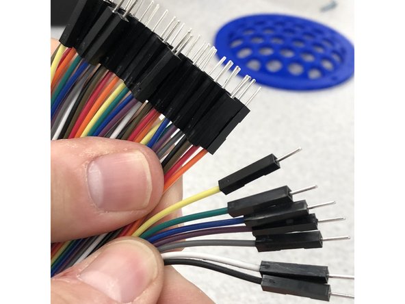
Take about 12" each of black and blue 22 guage wire. Strip the ends ~3/8"
-
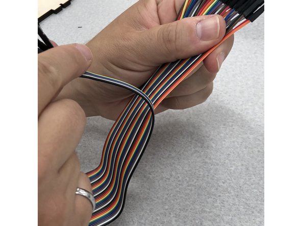
Take seven strands of wire ribbon. Keep them attached to each other, but separate slightly at the ends.
-
-
-
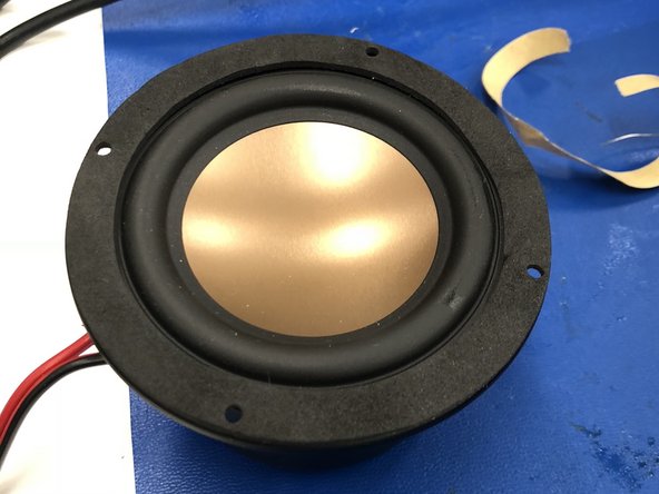
Attach the rubber gasket to the lip of the speaker, taking care that the screw holes align.
-
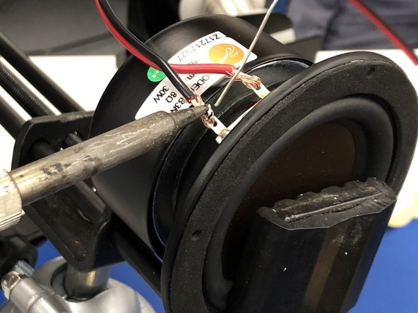
With one of the 1' wires, using the 1" stripped end, loop the red wire through the red terminal (marked by a red dot) on a speaker and crimp back with pliers.
-
Repeat with the black wire on the other terminal.
-
Align the wire along the magnet of the speaker, like it is trailing behind the speaker if it was flying forward. Solder the terminals to the wires. Repeat with the second speaker.
-
-
-
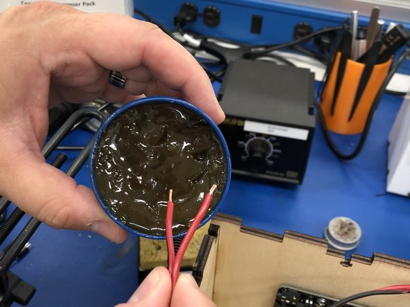
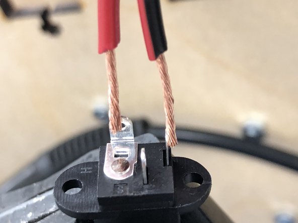
Using the remaining 1' wire, very tightly twist the wire ends. We are going to pre-tin the wires and leads with solder.
-
Dip in flux, then melt a drop of solder onto each of the ends and the side-facing lead (red) and the bottom lead (black)
-
Slide two ~1" segments of heat wrap over each wire. We will shrink these on after soldering to protect the wires.
-
Solder the black wire to the bottom lead and the red to the side. It might be helpful to have a partner hold the wires while you solder.
-
Do not let ends touch!
-
Slide one of the heat wrap segments over each of the two connections that you have just soldered. Warm with a heat gun briefly to secure the wrap.
-
-
-
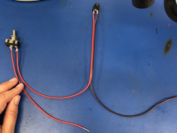
Take the wire that you have just soldered to the barrel jack.
-
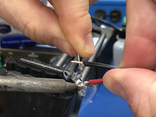
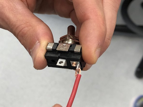
Solder the other end of the red wire to one lead of the power switch.
-
Take the red wire previously prepared, solder that wire to the other lead of the power switch.
-
Slide the remaining two heat wrap segments over each of the two connections that you have just soldered. Warm with a heat gun briefly to secure the wrap.
-
-
-
Remove the rubber bands from your speaker box. It's unlikely the glue is fully cured, so be gentle. However, it should be acceptably stable to work with at this point.
-
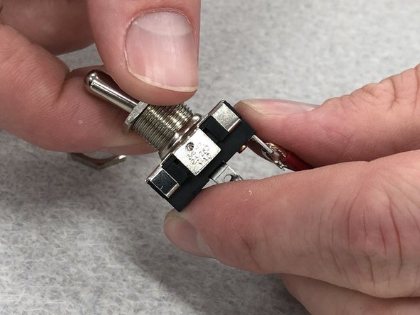
Take the switch assembly and remove the panel mount nuts from the switch.
-
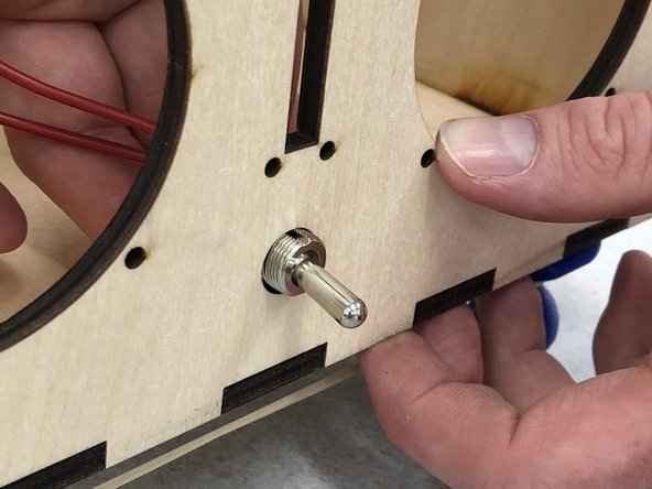
Insert the switch in the switch-hole in the front of the speaker, and reattach the mounting nuts.
-
-
-
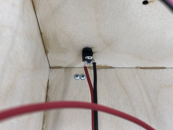
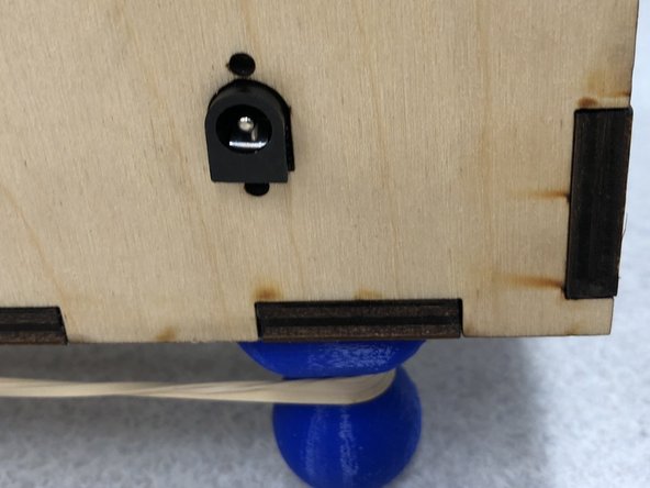
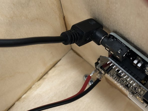
Put the barrel jack through the hole on the back of the speaker.
-
Use two 2-56 1/2" screws to hold the jack in place. This is the only time we use this size/configuration of screws. The nut should go inside the case.
-
-
-
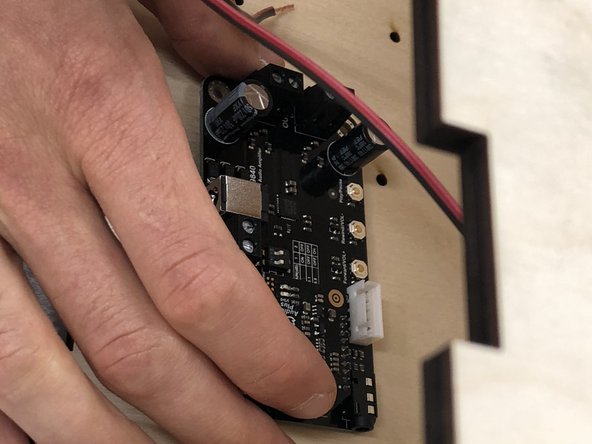
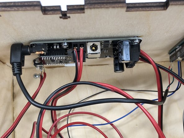
The amplifier board goes inside the speaker box on the back surface's left hand side as you are facing the front of the box.
-
Use three 4-40 1/2" screws to attach the board, with the hex nuts on the outside.
-
Connect the remaining black and red cord to the screw terminals at the top of the amp. The black wire goes into the left side (as you are facing the box), the red wire into the right (as you are facing the box). Tighten the screw terminals to hold the wires in place.
-
-
-
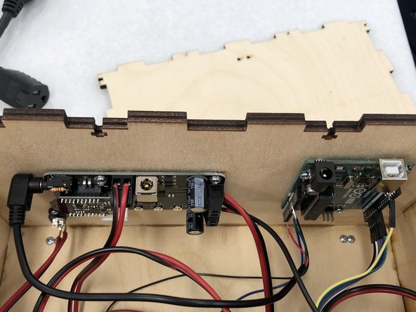
Attach the Arduino on the inside of the speaker box. It fits on the right-hand side (while facing the front of the box) on the back wall with the USB port facing up.
-
Use three 4-40 1/2" screws, with the hex nuts on the outside. The USB jack should point up. The hole closest to the barrel jack on the Arduino is not large enough for a bolt/nut so ignore it. Three screws will hold it.
-
-
-
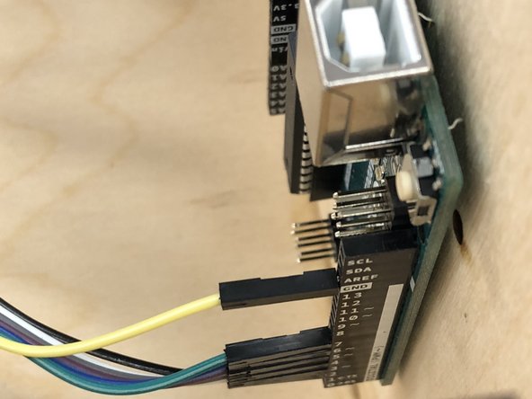
The ribbon cable will attach to the terminals on the right-hand side (as you face the box) of the Arduino.
-
The top wire should connect to the "Ground" (labeled GND) terminal hole.
-
The remaining wires should connect to slots 2-7. Keep the wires in original order.
-
-
-
The audio wire plugs into the audio jack in the upper-left corner of the amplifier.
-
Put the red wire into the "A5" terminal on the Arduino, and but the green wire into the a ground "GND" on the Arduino.
-
Secure the two audio wires to the Arduino terminals with a small drop of glue from the glue gun (use a popsicle stick to apply). Otherwise, these slip out easily.
-
-
-
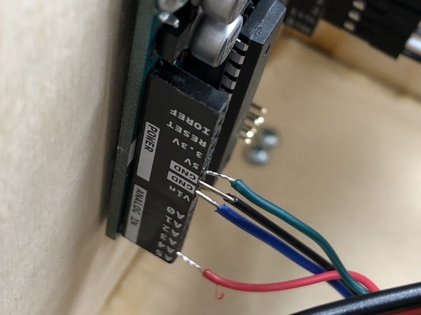
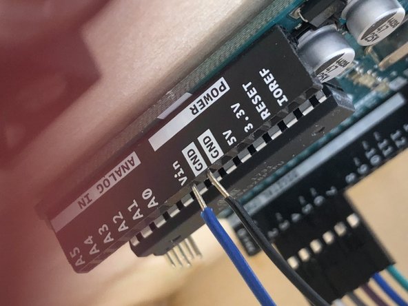
Using a blue wire and a black wire, attach one end to the (slot) on the left-hand side (while facing the front of the box) of the Arduino.
-
Insert the black wire into the other ground slot (labeled GND)
-
Insert the blue wire into the voltage in (Vin) slot
-
Note that the labels will be upside down as installed.
-
-
-
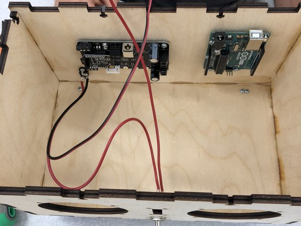
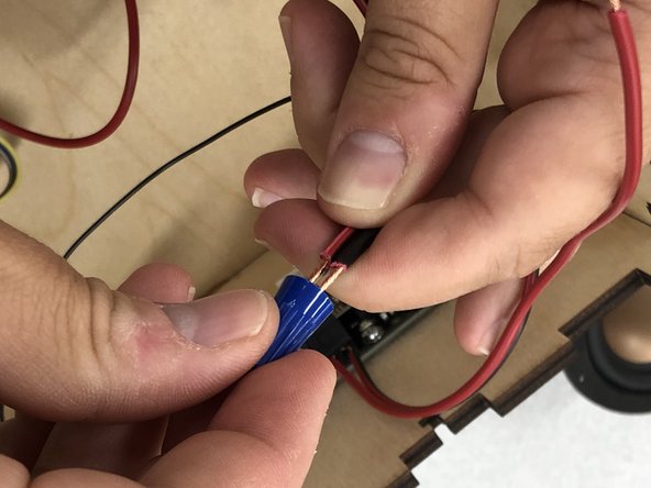
The three red power wires that emerge from the switch, the amplifier, and the Arduino will be connected with a wire nut. Note the "red" wire from the Arduino is blue.
-
Gather and twist the ends of the three red wires together, then screw on the wire nut.
-
The three black ground wires that emerge from the Arduino, the amplifier, and the barrel jack will be connected with a second wire nut.
-
Twist the ends of the three black wires together, then screw on the wire nut.
-
Ensure that the wires are securely in the wire nut. Give each a tug. They should not come out. If they do, unscrew the wire nut and try again.
-
-
-
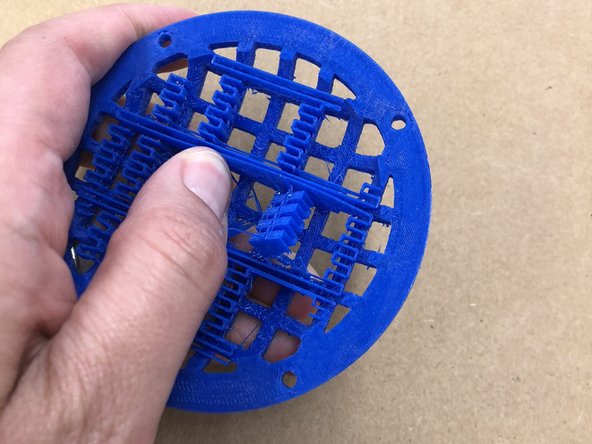
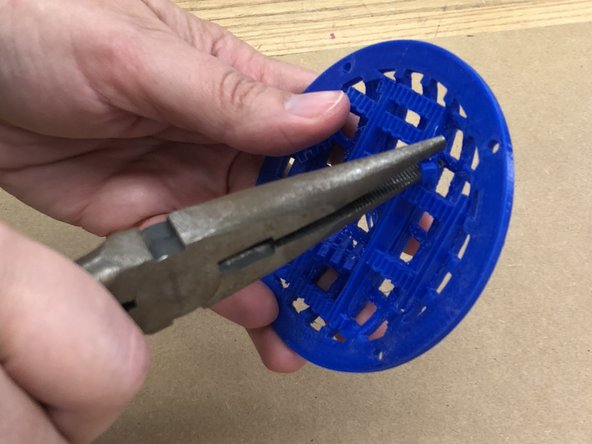
Remove the support material from the speaker grilles.
-
Using needle-nose pliers (or your hands, but we recommend the pliers), break off the support material from the underside of the domed speaker grilles.
-
If you are unsure which parts are support material, they should break easily. If you find yourself exerting significant effort, check that you are not breaking the grille.
-
Use some sandpaper or a small file to remove any remaining frayed edges of the support material
-
-
-
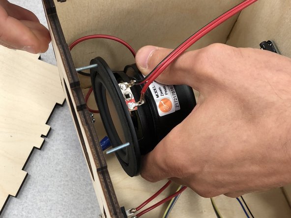
The speakers will be inserted from the inside of the box. Attach the speakers with 5/8" screws. It's most helpful to put the screws in the speaker (from back to front) before you insert them into the box, then align with the screw holes in the top. The leads should point to the top.
-
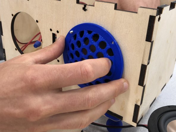
Put the grille on the front of the speaker. Use a screwdriver to hold the screws in place, and hand tighten the nuts.
-
-
-
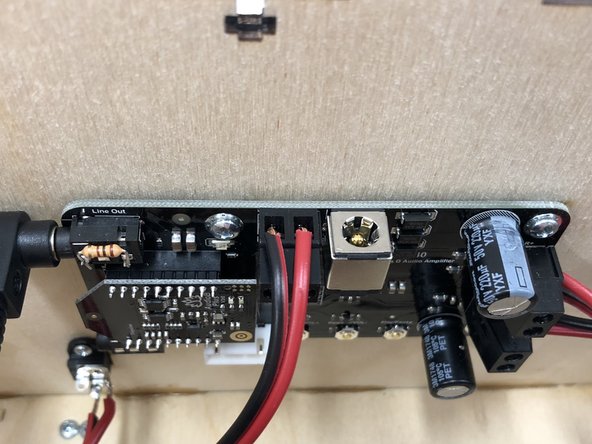
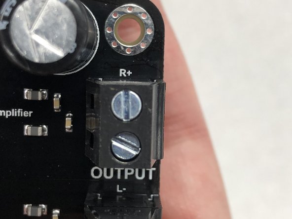
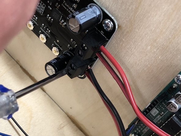
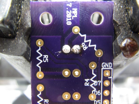
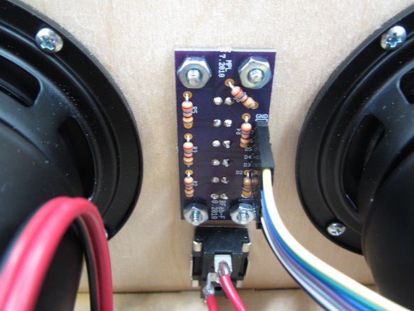
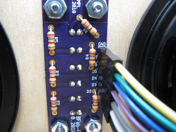
Connect the speakers to the amplifier. The first image is a close-up of the top screw terminals; the labels can't be seen when the amplifier is installed.
-
The connections for speakers are the screw terminals on the right-hand side (as you face the box) of the amplifier. The "left" speaker is the top two slots, the "right" speaker is the two on the bottom.
-
Start from the bottom. Connecting your left speaker, thread the red wire into the bottom slot and the black wire into the next slot up. Screw the leads down with a small flat-head screwdriver; the ole' righty tighty applies.
-
For the right speaker, put the black wire into the next slot. Insert the remaining red wire in the top slot. Screw the leads down.
-
If the terminal is not open far enough to insert the wire back the screw out. Don't go too far or the screw may fall out, though.
-
-
-
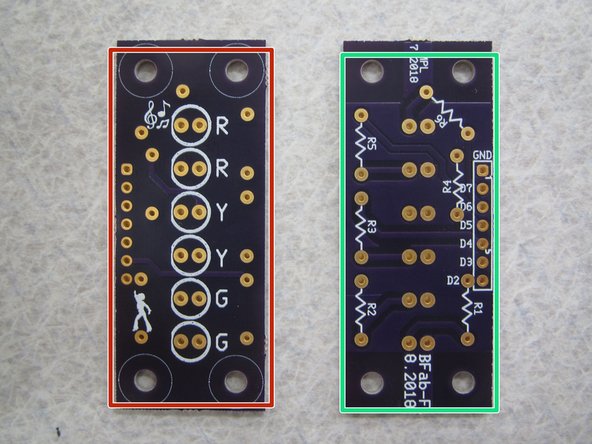
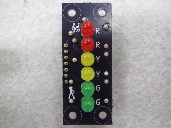
Locate your VU meter printed circuit board (PCB ). Notice that it has a:
-
FRONT
-
BACK
-
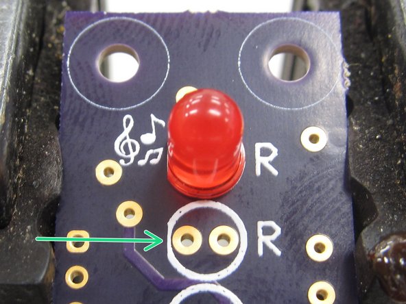
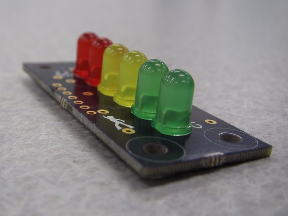
Begin by soldering the six light emitting diodes (LEDs). Insert the LEDs from the front so that the plastic case sits on top of the white circular silkscreen and the legs or leads stick out the back of the PCB.
-
-
-
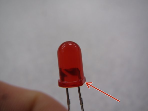
Diodes are polarized devices with an anode and cathode. This means that when you solder them in place you must pay attention to how you orient them.
-
In order to determine how to properly orient the LED, look at the plastic case. One side will have a small, flat edge.
-
Be sure to line up this flat edge with the flat edge on the silkscreen layer on the top side of the PCB.
-
-
-
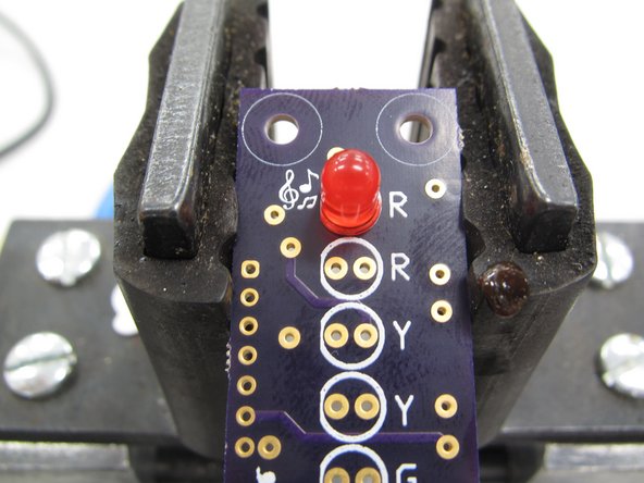
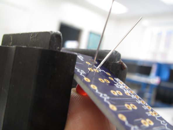
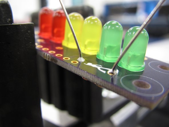
It is best to clamp the PCB in a vice to provide a sturdy base against which you can apply adequate pressure while soldering.
-
The vice also allows you to push up on the plastic case of the LED to keep it flush while soldering in place.
-
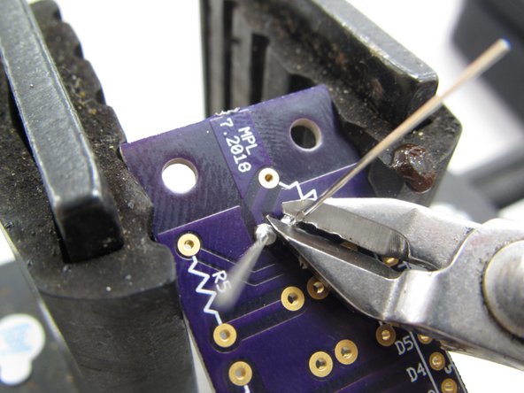
When you have successfully soldered both leads be sure to clip them flush with the PCB.
-
-
-
Solder the LEDs one at a time. When you are finished your PCB should look like the example shown here.
-
-
-
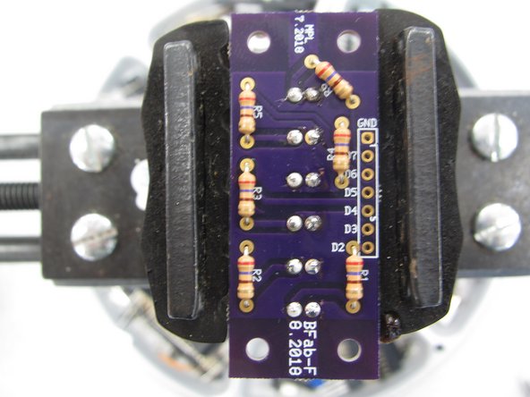
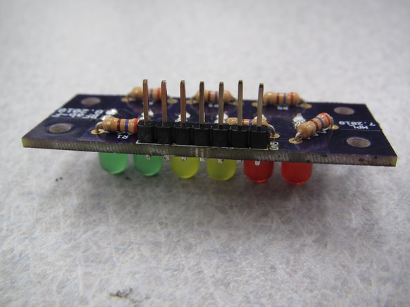
Next you will solder the resistors on your PCB. Resistors are not polarized so their orientation does not matter.
-
Be careful! While the LEDs were in a plastic case which could be held by hand during soldering, the ceramic resistor case WILL GET HOT during soldering. Do not touch the resistor while soldering!
-
Each LED has its own current limiting resistor. All six resistors are of the same value.
-
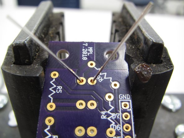
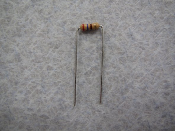
Choose a resistor and begin by bending its two leads down at a 90 degree angle flush against the ceramic body.
-
Next insert the resistors from the bottom of the PCB so that the leads stick up from the top of the board. Note that this is opposite the insertion of the LEDs. DO NOT SOLDER THE RESISTORS ON THE SAME SIDE AS THE LEDS OR YOUR PCB WILL NOT FIT PROPERLY IN YOUR SPEAKER ENCLOSURE.
-
-
-
While the resistors are not polarized and their orientation does not matter from a functional standpoint, it is still best practice to keep them all oriented in the same direction.
-
Keeping components of a similar type oriented in the same direction aids in any potential troubleshooting. With components in the same direction it is easier to read markings or other indicators on the component packages.
-
The completed example shown here has all of the resistors oriented in the same vertical direction, with the top right resistor rotated slightly counter clockwise.
-
-
-
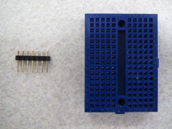
The final component to be soldered is the 7-pin strip of header pins.
-
While it is possible to solder these without any special techniques it can be helpful to use a breadboard to keep the pins straight and flush with the PCB.
-
A breadboard will also provide a flat, rigid surface against which to solder. It also prevents you from having to use your hands to hold the pins in place and potentially burning yourself.
-
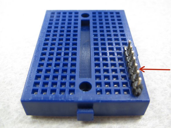
Begin by inserting the long end of the header pins into a breadboard. Be sure to place the pins on the edge of the breadboard and not in the middle.
-
-
-
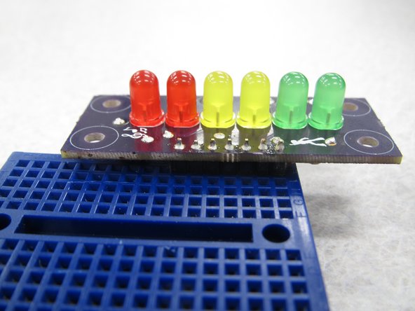
With your header pins securely inserted in the breadboard place your PCB on top of the pins.
-
Be sure to have the LEDs facing upright when you lay the PCB on top of the header pins.
-
Solder the seven pins in place and then remove the completed PCB from the breadboard.
-
-
-
Your completed PCB should look like the example shown here. Note:
-
LEDs are all on the top side of the PCB while resistors and header pins are on the back of the PCB.
-
LEDs are all properly oriented with their flat edges all facing the left edge of the PCB
-
All components are sitting flush with the PCB
-
Solder joints/leads are clipped flush with the PCB
-
Header pins are pointing straight down from the bottom of the PCB
-
-
-
In the "Arduino" session you will program the light show that accompanies your speaker!
-
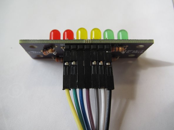
For now, it is sufficient to simply connect your completed VU meter PCB to your enclosure. Begin by attaching a 7-pin ribbon cable to your PCB header pins.
-
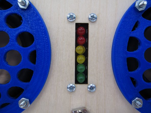
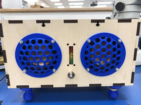
Next insert your PCB through the rectangular hole in the front panel of the enclosure. Point the LEDs out of the hole.
-
Use four 4-40 1/2" screws and 4-40 nuts to secure the PCB in place.
-
-
-
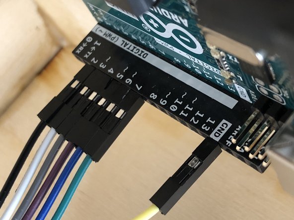
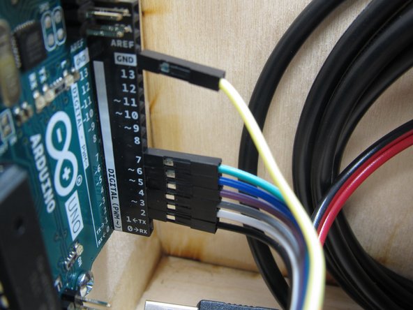
Connect the male end of the 7-pin ribbon cable to the Arduino.
-
Pay attention to the colors of the wires. Be sure to connect the GND pin properly between both devices.
-
Follow the silkscreens on the PCB and Arduino and make sure the wires match properly: D2 to D2, D3 to D3, etc. This will ensure that your LEDs light up in the proper order.
-
-
-
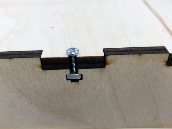
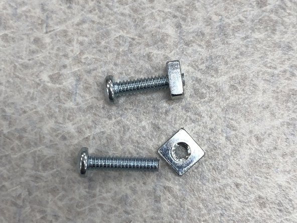
Pre-thread square nuts onto eight 1/2" screws.
-
Put the lid on your speaker box.
-
Place nut-and-screw assemblies into each of the keyholes in your box and finger-tighten.
-
-
-
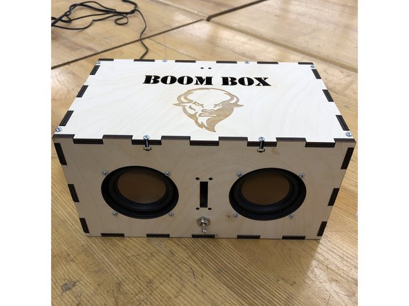
Plug in the speaker and power it on. You will hear a chime.
-
Using bluetooth, connect your phone
-
Rock out!
-
Note: we can't all turn it on for the first time at once, or you'll probably pair with the wrong speaker.
-


Bill of materials in the attached PDF.
Bill of materials in the attached PDF.