
Introduction
Software: SCAPS
-
-
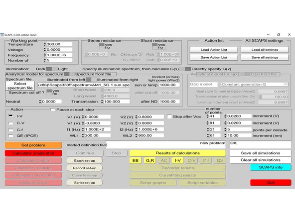
Open SCAPS 3.3.05. It starts with an “Action Panel” page.
-
-
-
Click on “Set problem” button (orange button towards the left of the screen) to define the cell layers. Upon clicking on the button, the “Solar Cell Definition Panel” opens up.
-
-
-
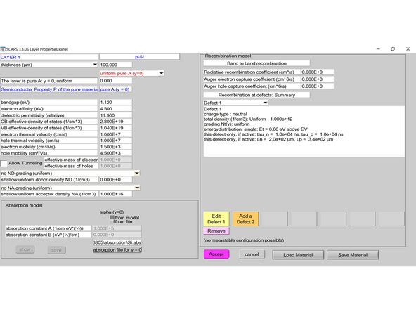
Click on the “add layer” button under the Layers section towards top left. The “Layer Properties Panel” lets the users set various parameters like thickness, bandgap, electron affinity, dielectric permittivity, CB and VB effective density of states, electron and hole thermal velocity, electron and hole mobility and donor and acceptor density.
-
-
-
Rename the layer to p-Si and alter the parameters as shown in the picture.
-
-
-
Apart from these basic parameters, users can also modify the absorption model, recombination model and add a defect to a layer. First set the absorption model to be from file and then select C:\Program Files (x86)\Scaps3305\absorption\Si.abs (the actual location of this file may vary).
-
-
-
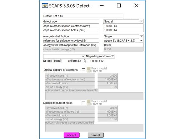
Next, click on “Add a Defect 1” near the bottom of the right half panel and enter the parameters as shown in the picture. Click on “accept” to finish editing the defect.
-
-
-
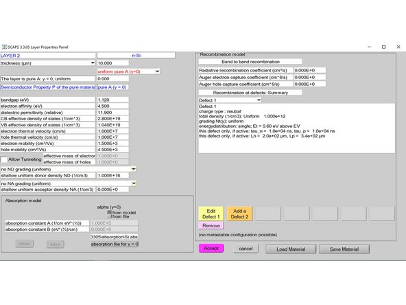
Click on “Accept” and you will return to the “Solar Cell Definition Panel”. Then click on “add layer” below the defined p-Si layer to add another layer. The “Layer Properties Panel” will show up. Similarly, rename it n-Si and alter the parameters according to the picture.
-
-
-
Again set the absorption model to be from file and select C:\Program Files (x86)\Scaps3305\absorption\Si.abs. Next, click on “Add a Defect 1” near the bottom of the right half panel and enter the parameters as shown in the picture. Click on “accept” to finish editing the defect.
-
-
-
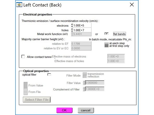
Click on “Accept” and return to the “Solar Cell Definition Panel”. Then click on “left contact (back)” to modify the left contact. Change the parameters as shown in the picture. Click “OK” when finished.
-
-
-
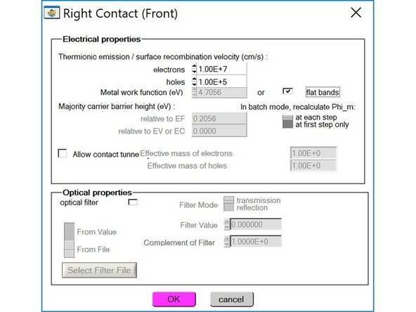
Click on “right contact (front)” to modify the right contact. Change the parameters as shown in the picture. Click “OK” when finished.
-
-
-
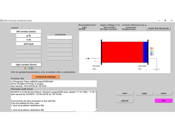
You will return to the “Solar Cell Definition Panel”. Check if the structure on the top-right corner is identical to the picture. If your red and blue layers of the solar cell are inverted, click on “invert the structure”.
-
-
-
Make sure that the settings above the structure are illuminated from right, apply voltage to left contact and current reference as a consumer.
-
-
-
Click on “save” button to save the structure for future use. You can save the .def file anywhere you want. Then click “OK” and you will return to main “Action Panel”. Notice there are three separate sections of options and parameters on the panel: “Working point”, “Illumination”, and “Action”.
-
-
-
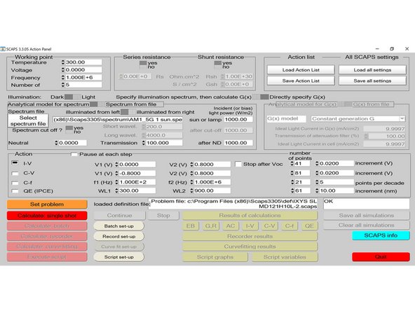
Make changes to the temperature, voltage, and frequency parameters in the “Working point” section if necessary according to the picture.
-
-
-
For the “Illumination” section, select “Light” and then select “Spectrum from file”. Click on “Select spectrum file” and choose C:\Program Files (x86)\Scaps3305\spectrum\AM1_5G 1 sun.spe (the actual file location may vary). Set the incident light power to be 1000 W/m2.
-
-
-
For the “Action” section, only select “I-V”. Set V1 to be 0V and V2 to be 0.8V as shown in the picture above. The default number of points is 41, but more or less points are both fine.
-
-
-
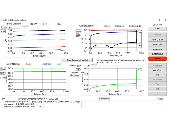
Click on “Calculate: single shot” (red button towards the left of the screen) and a new “Energy Bands Panel” will show up. Wait a few seconds till the simulation is done.
-
-
-
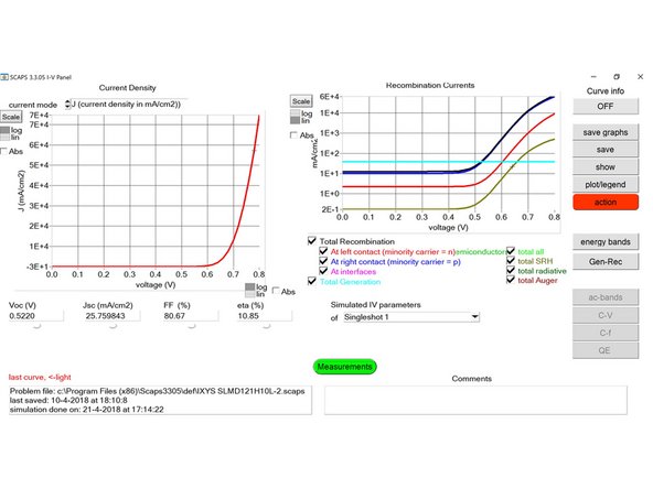
Click on the “I-V” option on the right side of the panel and the following “I-V Panel” will appear.
-
-
-
The “current density vs voltage” plot is shown on the left. Below the plot are the simulation results which include the open-circuit voltage, short-circuit current density, and fill factor. Compare your simulation results with the picture above. They should be the same if you use all the same parameters.
-
-
-
You can save graphs by clicking on “save graphs” and have the option to save the whole I-V panel or just a single plot.
-
-
-
Click on the “action” button and you will return to the main “Action Panel”. Click on “Save all settings” on the top right corner to save the .scaps file which can be loaded in the future by clicking on the “Load all settings” button. Finally click on “Quit” in the bottom right corner to exit.
-


Cancel: I did not complete this guide.
One other person completed this guide.