-
-
This project uses an IKEA "Lack" side table as the base for the gaming table.
-
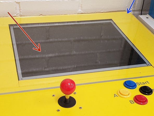
Follow the templates below to laser-cut holes in the table for the monitor, joystick, controls, and buttons.
-
Template for cutting screen window and button/joystick holes: https://drive.google.com/open?id=1fDV7cE...
-
Template for cutting "control box": https://drive.google.com/open?id=190PKk3...
-
Only "vector" settings are needed. The cutting material can be treated like 1/8" veneer.
-
The laser cutter will burn through the top layer of the table. Use the back of a hammer to remove the laser-cut screen and control windows, and a screw driver to remove the layer over the button, joystick, and cable holes.
-
-
-
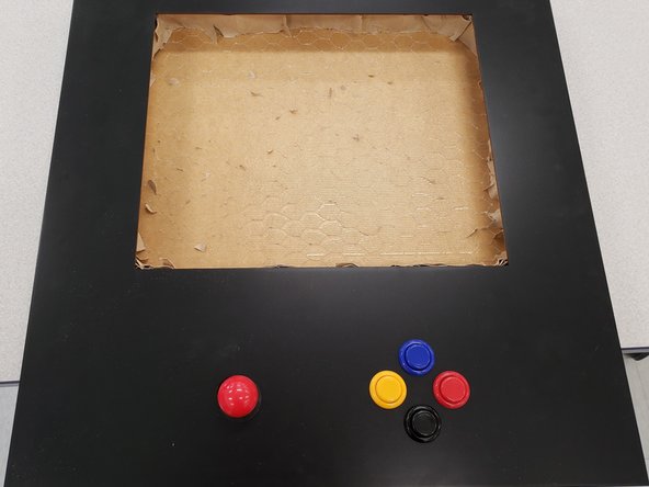
The next step after the tables are laser cut is to remove the cardboard filling.
-
Remove most of the cardboard; however, leave some along each of the sides of the screen and control windows.
-
Pack the remaining cardboard filling against the sides of the cut-out.
-
-
-
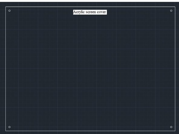
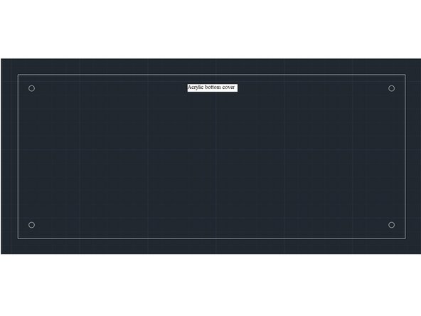
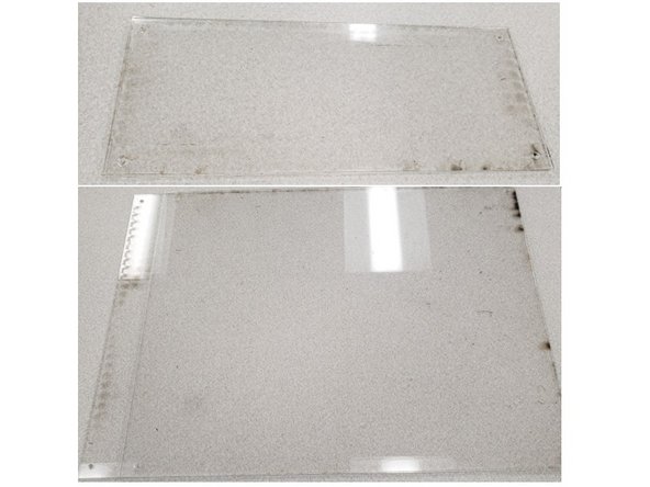
Laser-cut screen and control box covers from 1/8" acrylic.
-
Template for acrylic screen cover : https://drive.google.com/open?id=1ULFo0K...
-
Template for acrylic bottom cover: https://drive.google.com/open?id=1mqgwTT...
-
-
-
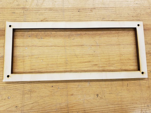
Next, cut three 1/8" wood frames. These will be glued to bottom of the table top, around the "control box" that you cut.
-
Template for wood exterior frame for the control window: https://drive.google.com/open?id=18worOj...
-
-
-
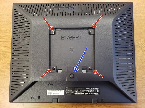
Press the black button and pull the base away from the monitor screen.
-
Remove the screws on the back of the monitor.
-
Follow the instructions in the following video to remove the casing from the monitor: https://drive.google.com/open?id=1--BjPh...
-
Be careful not to damage the circuit board under the bottom-right corner of the monitor.
-
Plug the monitor in and turn it on using the button strip. Leave the monitor on and unplug it, so that the monitor turns on when the gaming table is plugged in.
-
-
-
Place the monitor in the laser-cut, rectangular space on the top surface of the table. Screw in the top acrylic plate over the monitor and table.
-
Place the power box in the rectangular cut space on the bottom surface. Connect the power cable from the monitor to the power box.
-
Screw the bottom acrylic plate over the controls section.
-
-
-
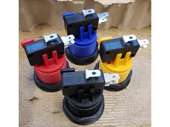
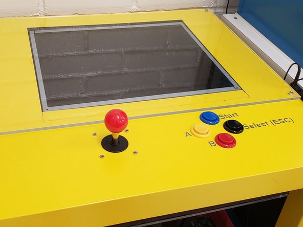
To attach a button, unscrew the nut, and place the button in the correct location. Screw the nut onto the bottom of the button to fasten the button to the table
-
-
-
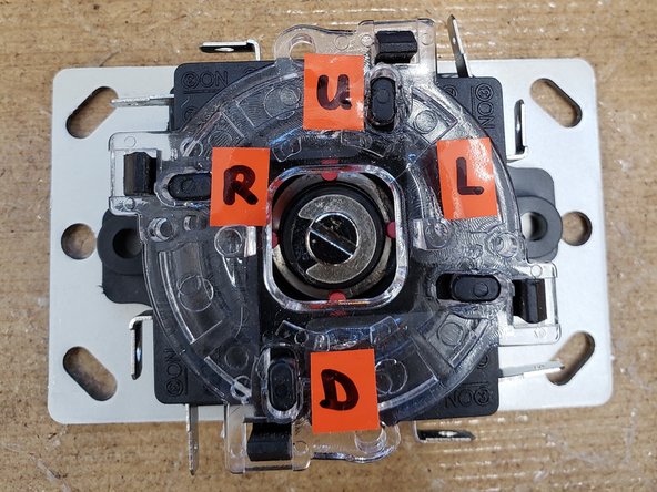
Label the four corners of the metal plate side of the joystick, with the each corner corresponding to the up, left, right, and down switches respectively. You can move the joystick to identify each switch.
-
Remove the black washer and the red ball from the joystick. Underneath the table, move the joystick to the location indicated by the laser-cut holes. Screw the red ball and black washer onto the above-table portion of the joystick.
-
-
-
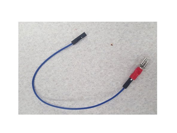
Crimp quick connectors to the male ends of nine male/female jumper wires.
-
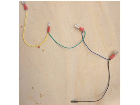
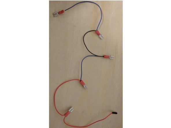
Make two daisy chains using the nine wires. Both will have a female end. One will have four wires and four connectors, and the other will have five wires and five connectors.
-
-
-
Use an HDMI to DVI to cable to connect the monitor to the PI (which should already have an imaged microSD card).
-
Additional information (not needed for this tutorial) for customizing the Retropie image: Customizing Raspbian Image
-
Use a USB cable to connect the raspberry PI (0 or 3) to the power.
-
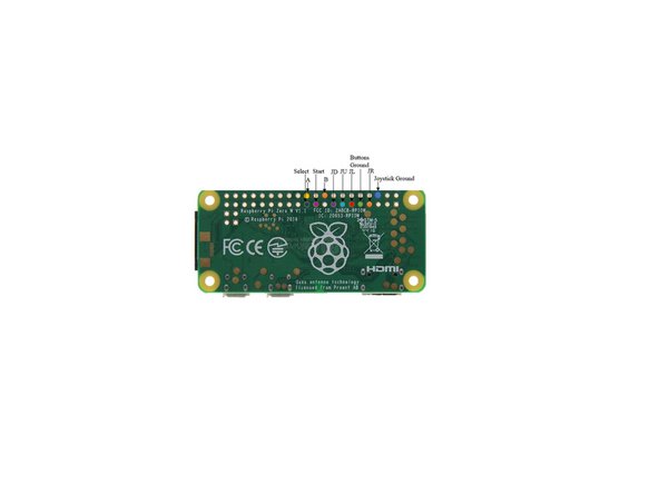
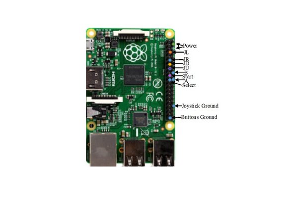
Wire the PI according to the appropriate diagram.
-
-
-
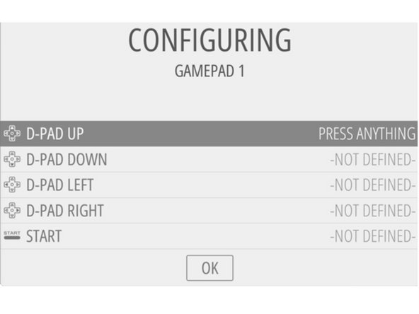
Once the gaming table is plugged in, the system will ask you to "configure input."
-
Press a button or move the joystick to correspond to the requested input. You can arrow down the configure menu by holding in the start button.
-