Introduction
The Maker PORTAL system is used to keep track of training records, track machine usage, and provide access control to machines in a MakerSpace. In this tutorial, you'll learn how to make the PORTAL box which is the hardware front-end of the system used to manage access control at each machine.
Depending on your parts sources and quantities, each portal box will cost about $100 to fabricate and must have wired or wireless internet to function.
The PORTAL box is not designed to completely secure a piece of equipment such as a cord cap or other lockout device. It can be over-ridden by users. Rather it is designed to provide a visual indicator of equipment status in a MakerSpace and indicate when an unauthorized users is accessing a piece of equipment.
Tools
Parts
No parts specified.
-
-
The Maker PORTAL box consists of three major components that need to be built/programmed separately then assembled.
-
A printed circuit board that should be ordered from a fabrication house. Links to files are later in this tutorial.
-
-
The enclosure consisting of an aluminum baseplate and acrylic case
-
Many of the parts needed are likely not on hand in your MakerSpace. A complete Bill of Materials can be found here.
-
To build a PORTAL box you will need access to electronic fabrication tools for the PCB, a laser cutter for the enclosure, ability to install the OS on a RPi, machine tools to cut aluminum and drill and tap holes accurately.
-
We recommend that you assemble each component in the order that they are presented in this list the first time you assemble a PORTAL box
-
-
-
We assume you have experience in electronic design, fabrication, and know how to send PC boards out for fabrication.
-
You can either send printed circuit boards out to be fabricated and solder components on yourself or have the PC board populated for you. Because we chose to have the surface mount components pre-soldered and did the through hole components ourselves, that is how this tutorial explains the process.
-
We used PCB Assembly Express to have our boards fabricated. There are many other PCB houses and the costs change so shop around to determine what your best options are.
-
If you order unpopulated boards you will need to have the equipment needed to solder both surface mount and through hole components. We recommend a having available a good quality soldering iron, rework station, pick and place, and PCB reflow oven.
-
All the files needed to have a PC board made as well as the schematic diagram can be found here.
-
If you are adding the surface mount components use the image above as a guide. The second image shows the board layout and can be used as a guide for soldering components. A bigger image is here.
-
-
-
Once you have done the surface mount soldering (or purchased pre-populated boards) note the following while hand-soldering:
-
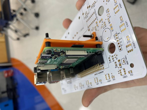
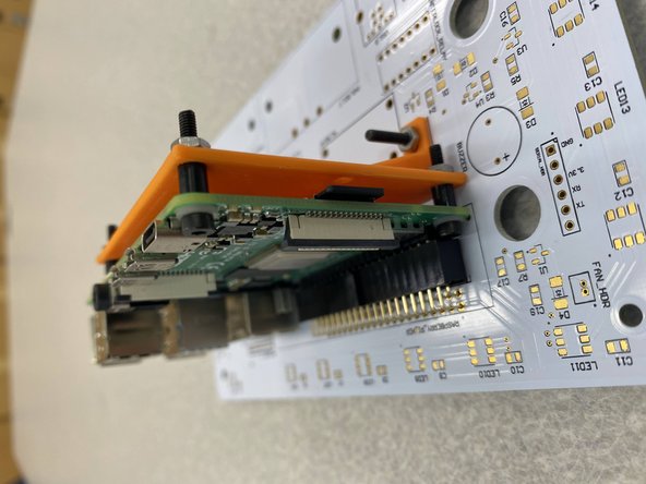
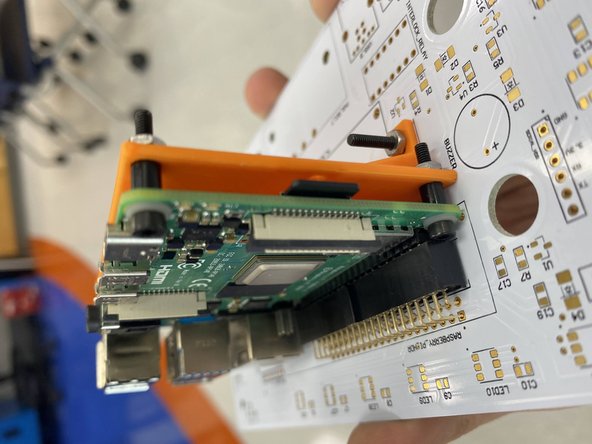
20x2 pin female header for RPi - Solder this first. Because the Pi is tall, the header needs to float a bit. We need to first attach the Pi mount, put the header on the Pi, attach it to the board via the screw holes, and then solder on the header to ensure a proper fit. Once this is done, you can dismount the Pi, leaving the 3D printed bracket on.
-
When removing the Pi from the board, leave the 3D printed bracket on, but remove the screws and simply slide the whole assembly out from the header.
-
Fuse holder - We recommend soldering the fuse holders with the fuse already in. This will help to ensure the spacing is correct.
-
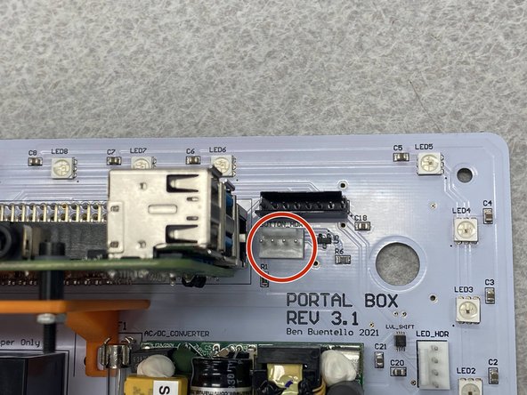
6 pin right-angle serial header - Ensure that when you put this into the board it has clearance over the LEDs. You may have to flip it around to ensure that it will clear them.
-
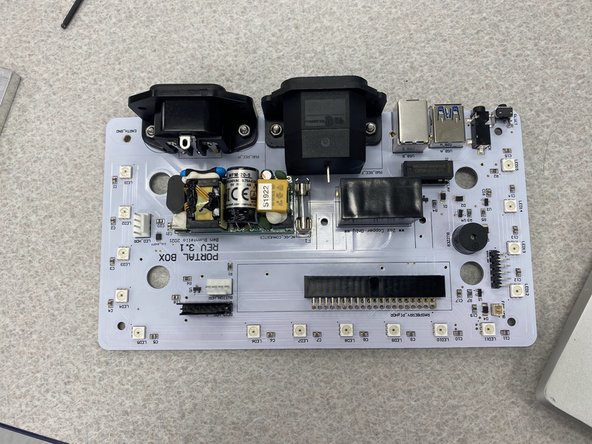
The second image shows each of these components soldered on the PCB.
-
You should be comfortable soldering parts on PCBs. Some of the connections will carry significant current and need to be correctly done with no bridges or bad joints.
-
-
-
When inserting the relays, ensure that the 8-pin relay is in the socket closer to the USB ports, with the dot matching the silkscreen. The dot should be in the corner nearest to the AC Relay.
-
The other socket takes two relays, which we used the G3VM-41AY1 for due to it's higher current capability. They should be side by side, oriented with the dot in the same corner as the 8-pin relay.
-
Ensure the relays are in the correct socket! Failure to do so may result in a cooked relay if a high-current USB device is connected.
-
-
-
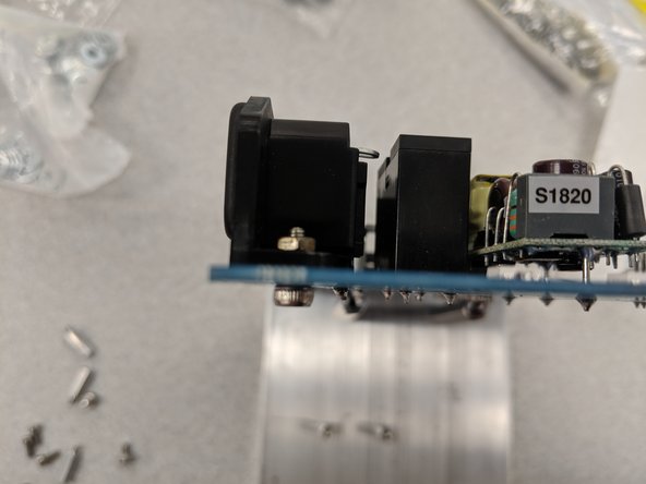
The last step in preparing the PCB is to secure the 110 VAC power entry (in) and egress (out) to the board even further with screws and nuts. This will ensure they can withstand the forces of cords being inserted and removed.
-
Use M3 8mm screws and the corresponding hex nuts to fasten the two components to the board. Make sure they are sufficiently tight.
-
The PCB is now ready for final assembly later on!
-
-
-
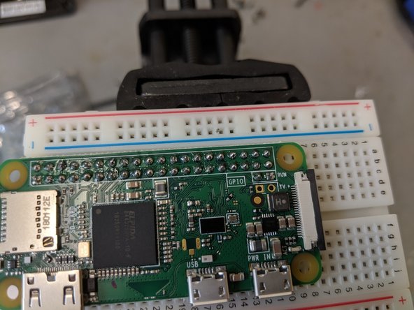
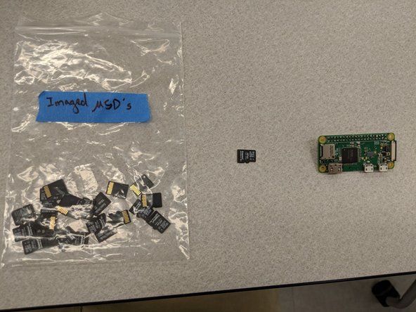
Next you need to image the micro SD card with the RPi OS. The instructions on creating an image are given on the Raspberry Pi site.
-
We recommend you get the latest version of Rasbian, ensure your networking configuration works and then install the PortalBox-application. Remember to enable the service via systemd!
-
After the micro SD and the pins are in place, the RPi is ready to be installed in the Maker PORTAL box. It is not a bad idea to boot up the RPi before installing it to make sure your configuration is correct.
-
-
-
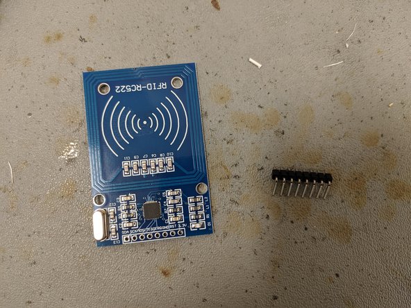
Solder a 90-degree 8-pin header onto the top of the RFID card reader. The short pins are soldered into the board and the longer pins should be parallel to the plane of the RFID board as shown.
-
Make sure you mount the connector on the side of the board shown since later the flat side of the RFID reader will be adhered onto the inside of the case.
-
-
-
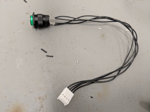
You will need four electronic hookup wires about 6 inches long with the ends stripped. We recommend stranded wires. Solder a Molex pin on one end of each of the four wires.
-
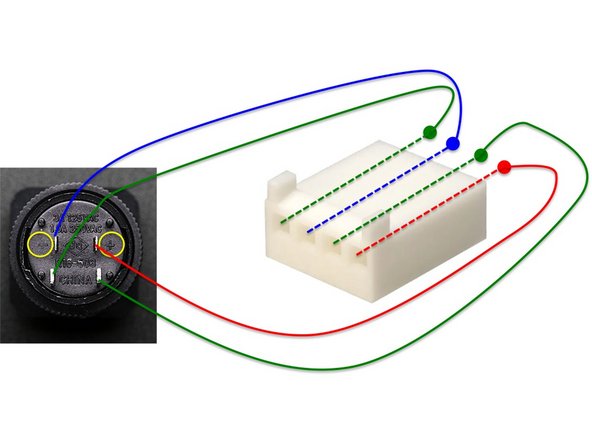
The first image shows the connections between the connector and button. The lower pins are for the button and the other two pins labeled + and - (in yellow circles) are for the light.
-
Use the wiring diagram in the first figure to match the wires from the button to the correct holes in the connectors. The second figure shows how the wires should connect to the PCB.
-
Push the pins attached to the wires into the header making sure to follow the order in the first figure. Make sure you get the positive and negative wires correct, the symbols are identified in the yellow circles.
-
When complete the assembled button should look like the third figure.
-
If you get the order wrong by accident, it is easier to desolder the wires from the button rather than try to remove them from the connector.
-
-
-
The baseplate of the Maker PORTAL is made using 1/4" x 4" aluminum bar stock which can be purchased from many metal vendors such as Speedy Metals.
-
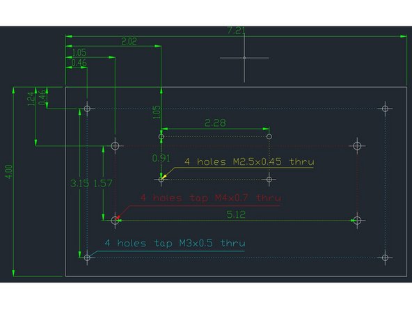
Buy the barstock pre-cut or cut it yourself to a length of 7.21 inches. You will then need to drill and tap holes using the dimensions shown in the second figure. Details are in the files here.
-
Given the tight tolerances we recommend you use a mill to prepare these files. You can also use drill press with a 1:1 scale paper template and a punch to center holes. If you use a template adhere it to the baseplate with rubber cement.
-
The components we use in the next steps are metric, but similar sized standoffs with English measurements can be substituted. Read ahead and make sure you have the drill and tap sizes needed before you start.
-
If you are not comfortable using machine tools please do not attempt to create your own baseplate! These tools are potentially hazardous.
-
-
-
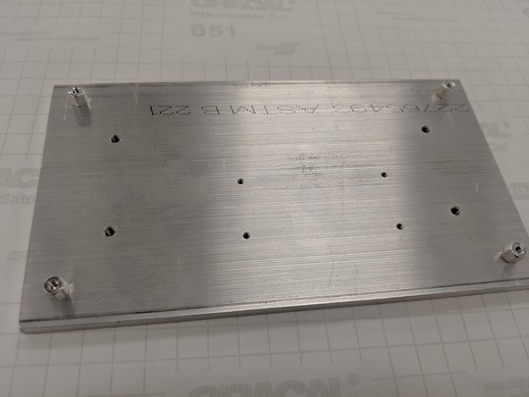
It is recommended you use blue Loctite to secure the screws/standoffs in place. Apply to the threads of the screws/standoffs as you insert them.
-
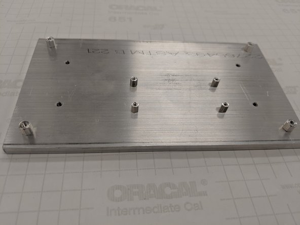
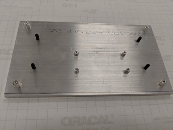
Screw in the M3 standoffs into the outermost four corner holes of the baseplate. These will be used to hold the PCB in place.
-
Screw the M2.5 standoffs into the four rectangular pattern holes offset from the center of the baseplate as shown in the last figure. These will be used to support the RPi.
-
-
-
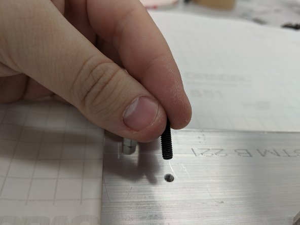
Secure the M4 set screws in the M4-threaded holes. These are will hold the long standoffs that support the box enclosure.
-
Orient the screws so that the hex wrench hole is facing down towards the bottom of the baseplate.
-
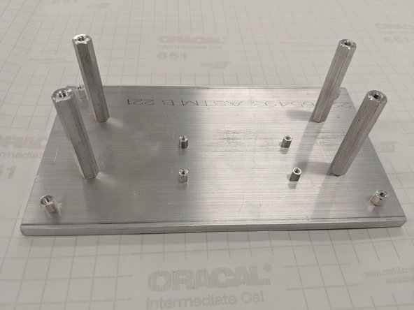
After screwing the M4 set screws in, thread the tall enclosure standoffs on each of the setscrews you just attached.
-
-
-
If you are using Loctite it will take about 24 hours to fully cure. You may continue with the next steps before the glue cures if you wish.
-
The assembled baseplate should look similar to the figure.
-
-
-
You will need two types of acrylic sheet to create the PORTAL box. One sheet of translucent white acrylic (#2447, the highest light transmission) 0.25" thick, and one sheet of clear acrylic, 0.125" thick.
-
The box itself is held together using 3M VHB tape. We recommend this tape over glue since it is easier and does not expose you to toxic chemicals.
-
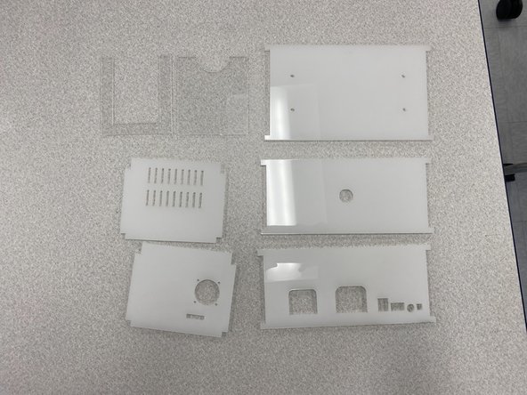
The PORTAL box will require that seven parts be cut, five of translucent acrylic and two of clear acrylic.
-
The enclosure itself is made from translucent white 1/4" acrylic plastic.
-
A two-part RFID card holder is made of clear 1/8" acrylic plastic.
-
The .svg files for all these parts are provided here. Solidworks files which can be modified are here.
-
The parts can be easily fabricated using a laser cutter. We recommend keeping the paper backing on while you cut to minimize smoke discoloration.
-
Make sure to set the text to be engraved rather than cut on the top and right sides. They will help you put together the box in the correct way later.
-
-
-
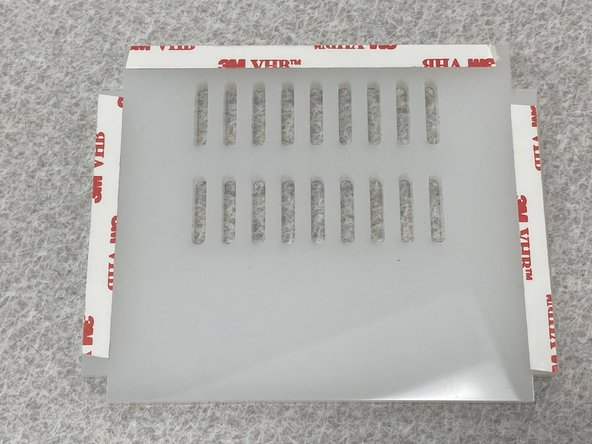
After cutting all the acrylic parts on the laser cutter then removing the paper backing, apply the 3M VHB tape on three sides of one of the side plates as shown in the first figure.
-
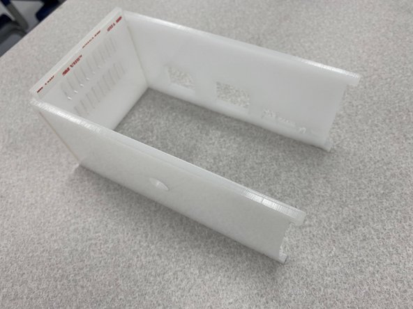
Remove the protective paper from the VHB tape on the two sides and adhere the front panel (round hole) and back panel (rectangular cutouts) onto the side panel as shown in the final figure.
-
VHB tape is very strong! Pay attention to the orientation of the back panel before you attach it. It's a good idea to compare it to the finished PCB to make sure components line up properly. If you get the orientation wrong, you will have to tear off the back panel and try again.
-
-
-
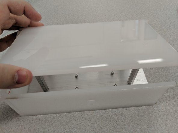
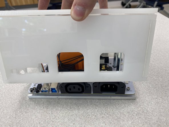
Slide the three sides over a completed baseplate. This will let you check orientation of the top panel.
-
Note that the four holes on the top panel are off-center so you must orient the top to the standoffs on the baseplate before attaching it with VHB tape. Looking down from the top you should be able to see the screw holes as shown in the second figure. If not, flip or rotate the top cover plate until the holes line up.
-
Add VHB tape to the top of the three sides you just assembled. Now being careful of alignment, attach the top panel onto the side panel, making sure that the threaded holes of the long M4 standoffs line up with the holes of the top panel.
-
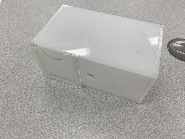
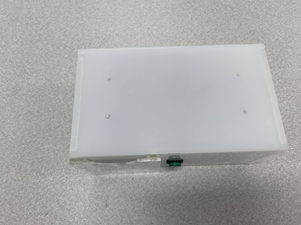
When the top panel is on correctly, remove the baseplate, add more strips of VHB tape, and adhere the final side on the enclosure. When complete it should look like the third figure.
-
-
-
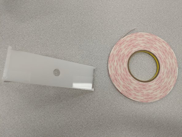
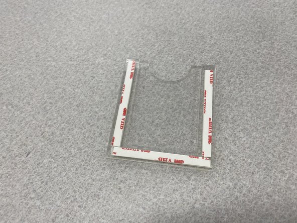
Use three strips of VHB tap to attach the U-shaped clear spacer to the card holder as shown in the first figure.
-
Add three more strips of VHB tape to the other side of the spacer to attach this assembly to the enclosure.
-
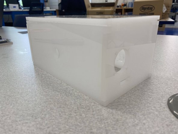
Being careful to align the card holder as shown in the second figure, attach the complete card panel to the left side of the front panel. Make sure to leave some space for the push button (about 1/4" from the hole, minimum)
-
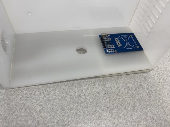
Using VHB tape or a 3M foam sticky square, attached the RFID card reader onto the inside of the front panel in the top right corner as shown. Make sure the pins are oriented as in the third figure and leave room for the push button. The RFID reader must line up with the card holder.
-
Also make sure the RFID card reader is high up enough (> 1/4") so that you can slide the enclosure onto the PORTAL without the card reader obstructing the enclosure.
-
-
-
Unscrew the plastic nut from the pushbutton and thread the button through the hole on the front panel.
-
Secure the pushbutton in place by screwing the plastic nut back on and tightening it.
-
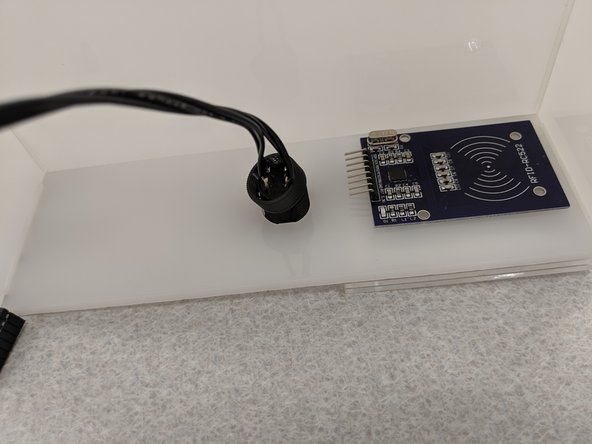
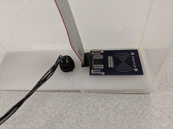
Attach the 8-pin ribbon cable wires for the RFID card reader.
-
Make sure you note the orientation of the wires (see second figure) to attach the connector correctly to the PBC. Double check the labels on both the RFID board and PC board.
-
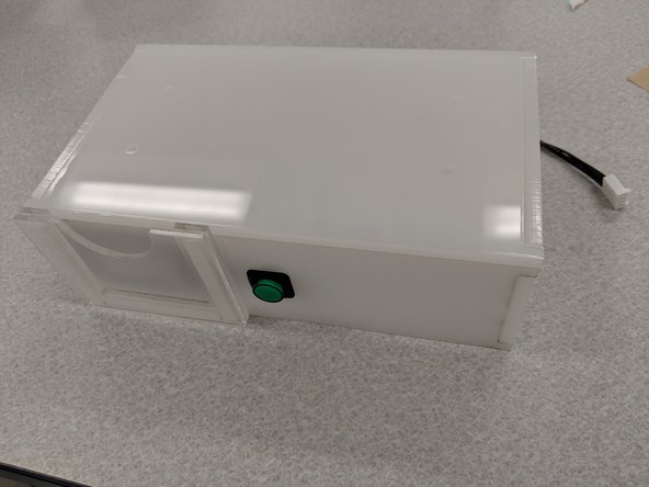
This completes assembly of the PORTAL box enclosure.
-
-
-
Insert the RPi into the 20+2 pin header on the PCB.
-
Secure the RPi onto the PCB using the M2.5 screws.
-
Make sure that you have an imaged micro SD card in the RPi. Once you secure it onto the board with the screws, you will have to unscrew it and take the RPi off if you want to switch out/add a micro SD.
-
-
-
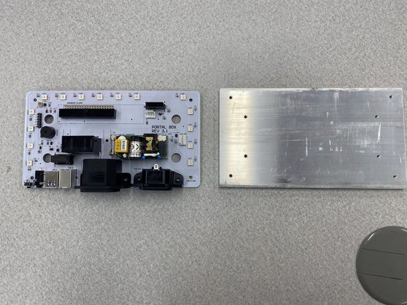
Get all the parts together you created in the previous steps:
-
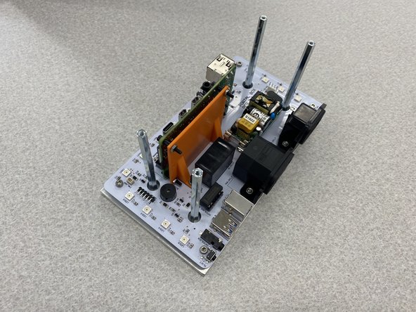
The finished PCB (shown here placed on top of the baseplate)
-
The prepared RPi
-
The baseplate
-
The completed acrylic shell with pushbutton and card reader installed
-
All other components listed in the BoM that haven't been used up to this point
-
-
-
Slide the PCB over the long standoffs and onto the baseplate, making sure to line up the holes for the RPi with the M2.5 standoffs. It should look like the third figure.
-
Secure the PCB onto the baseplate using 5mm M3 screws as shown in the second figure. If you don't see the holes you will have to rotate the PCB on the baseplate 180 degrees.
-
-
-
Take the enclosure and slowly and gently place it over the entire setup, making sure to keep the wires inside the box.
-
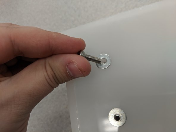
Place a washer on top of each of the four holes on top of the enclosure as shown in the second figure.
-
Screw the M4 screws into these holes.
-
-
-
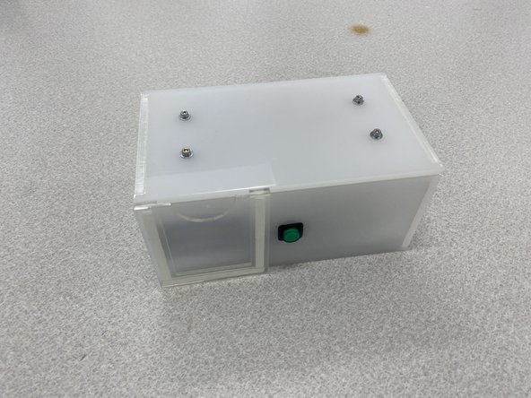
Congratulations! You've successfully constructed a Maker PORTAL box from start to finish.
-
You can now plug in the universal power cord and the IEC C14 to NEMA 5-15R adapter cable. Plug the universal power cord into a 15A outlet and the adapter cable into the device you are controlling the power for.
-
If you would like to use an interlock then use a 3.5 mm audio cable. When the portal box is activated, the internal relay will close.
-
Note that no AC power should flow through the 3.5 mm jack. Only use the interlock if you are familiar with wiring this up on the piece of equipment you wish to use!
-
You may use the USB in and out ports to interrupt data flow unless the PORTAL box is activated. This is useful for disconnecting a computer from a piece of equipment.
-
For more instructions on hooking up and using a PORTAL box, watch the video!
-