
Tools
Parts
No parts specified.
-
-
You will receive a robot kit.
-
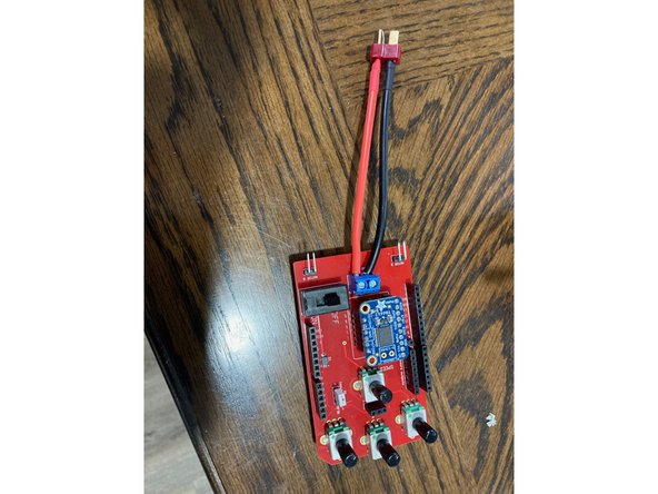
It should contain: a red chassis kit, a battery, a Dean's connector (battery connector), a 3D printed chassis mount that will hold the battery, a bolt and nuts to attach chassis mount, four rubber bumpers, two nuts, bolts, and spacers for the arduino, and an arduino shield.
-
There will also be a strip of IR reflectance sensors and some wires, but they will not be used for Assembly #1.
-
-
-
If the wheels and motors have already been assembled, make sure all the screws are tight and continue onto the next step. Otherwise, proceed to the following instructions
-
Tools you will need: small Philips head screwdriver, Philips head screwdriver
-
Using the provided screws and the small screwdriver, attach the rear motors into the shaped holes on the back sides of the chassis. The angled side is the front of the chassis.
-
When attaching the rear motors, make sure to orient them so that the control wires face the rear of the robot
-
Put together the two large wheels that will be the robot's back wheels by placing the treads on the wheels. In one side of each wheel's center there are ridges. That part fits onto the axle, which should not be visible when put together. Tighten the screws so that the wheels won't wobble.
-
Have the professor or TA check that the motor wheels are attached correctly
-
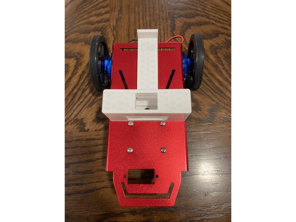
Using the provided screws and the larger screwdriver, attach the front wheel. There are four holes toward the front center of the chassis. The wheel spins, so the orientation does not matter. What side of the chassis you attach it to does matter, however, so be sure to put it on the bottom (see pictures).
-
-
-
Tools you will need: 3/32” Hex end wrenches
-
The chassis mount should have been already printed and brought into the lab. If not, the .stl can be found here.
-
Use the nut and bolt (same as for the arduino) to attach the mount to the center slot of the chassis. Slide it forwards against the front wheel screwheads and tighten.
-
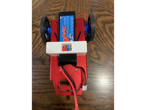
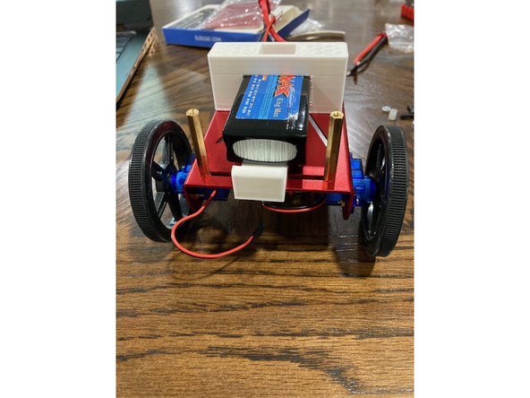
The battery should fit into the mount. Slide it in with the wires towards the front.
-
There will be two gold metal standoffs in the chassis kit. Attach them in the slots at the back with the provided screws from the underside of the robot.
-
-
-
Tools you will need: 3/32” Hex end wrench, pliers, Phillips head screwdriver
-
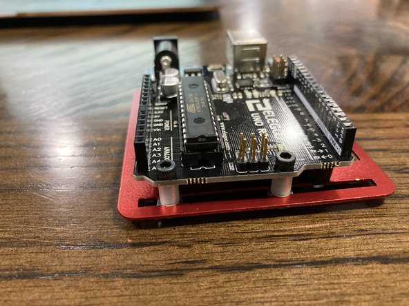
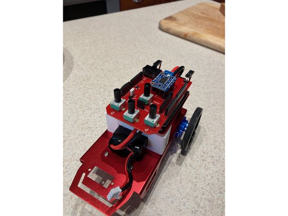
If your Arduino does not already have them, stick the rubber bumpers to the bottom to protect it from shorting or scratching the grate.
-
Use two nuts, bolts, and spacers to fasten the front of the Arduino to the grate.
-
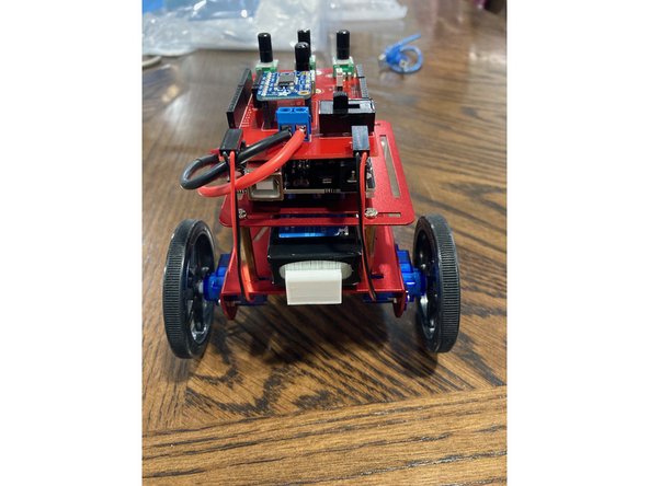
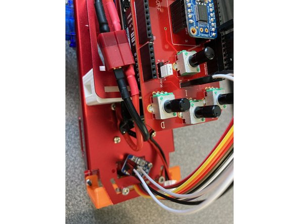
The assembled grate should fit right on top of the standoffs and chassis mount. The front of the Arduino should be towards the front of the robot. Use the matching standoff screws to fasten the back of the grate to the chassis.
-
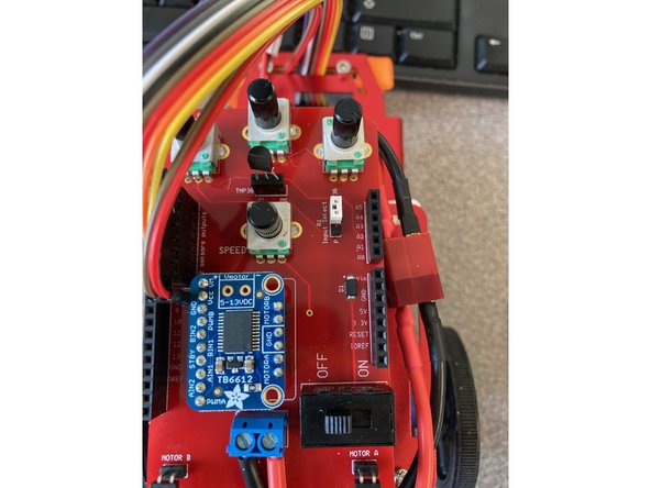
Attach the motor driver into the arduino shield. It should only fit one way.
-
Plug the Dean's connector into the terminal blocks at the back of the shield and fasten with a screwdriver
-
Be very careful to attach red to positive and black to negative.
-
Attach the shield to the Arduino. The pins coming out of the bottom should match up with the headers on the top of the Arduino.
-
-
-
Tools you will need: small flat head screwdriver
-
It is very important to make sure that the switch on the motor shield is turned off!
-
Plug in the battery to the Dean's connector.
-
Plug in the two motor wires to the right angle header pins on the back of the shield. The red wires should be on the right side of the right angle header pins.
-
Now, hook up the arduino to the computer making sure that the switch on the shield is still set to off.
-
-
-
Download this sketch. It will have some functions written at the bottom, but otherwise will be empty.
-
There are six pins on the motor driver that we care about to drive the robot. PWMA, Ain1, Ain2, PWMB, Bin1, and Bin2.
-
PWMA is pin 11, Ain1 is pin 12, Ain2 is pin 13, PWMB is pin 10, Bin1 is pin A4, Bin2 is pin A5.
-
Note that the motor A inputs are digital pins and motor B inputs are analog pins that need to be declared with an "A"
-
Declare int type variables for each pin. Also initialize a double for speed (100), a double for turn ratio (0 for now), and a boolean for the off-wheel turn direction(1 for now).
-
Do not call speed "speed". It will work, but it is bad practice to name variables with the same name as existing functions. If you try it, you will see that the variable name is highlighted. Use something else instead. The same goes for variable names such as "A1" and "B1". It isn't as obvious, but they should not be used either for similar reasons
-
-
-
In your setup function, set the pin mode of each motor driver variable to output.
-
Start the serial interface with a baudrate of 9600.
-
-
-
The motor driver is able to send the signals to the motors without the need for any added Arduino libraries.
-
Instead, you will be calling functions that set the direction your robot will go. The direction functions send commands to the motor driver through the runMotor function.
-
Motor A is 1, Motor B is 0; Speed is how fast out of 255; Forward is 1, Backward is 0; turnRatio is the speed of the off-wheel in comparison to the turning wheel; and turnWheel is the direction of the off-wheel, forward for wide turns, backward for sharp turns
-
Replace turnRatio and turnWheel with the variable names you came up with, but not spd, which is a separate variable that only exists in the direction functions.
-
-
-
This is the function that runs behind the scenes and actually outputs the commands to the motor driver.
-
This function essentially just writes the high and low values from the direction functions as digital outs and sends the speed as an analog out to the motors.
-
Replace the variables for the motor driver pins (pwma, ain1, etc.) with your own.
-
-
-
Have the professor or TA verify your code is set up.
-
-
-
Now that you understand the code for directions, actually driving the robot is super simple.
-
In the loop function, to make the robot go in a direction, you call that direction function with your speed variable as its parameter with a delay function after:
-
backward(speed_variable); delay(2000);
-
The example will make the robot drive backward for 2 seconds, over and over again (because it's a loop). You can add other directions to the loop for different amounts of time. If you wish to pause between movements, simply use another delay function.
-
After you upload, the robot will try to drive, but it won't be able to. Disconnect it from your computer then switch on the power on the shield.
-
-
-
Make your robot drive forward for 3 seconds, then demonstrate to the professor or TA.
-
-
-
Before plugging the arduino into the computer again, be sure to switch off the power on the shield.
-
At the beginning of writing the motor code, you initialized a variable for the turn ratio and off-wheel direction. You then saw how they fit into the code that runs the motors.
-
For example, while turning left, I might want to make a sharp turn, so I will have the left wheel turn backward at half speed while the right wheel turns at full speed. If I want to make a wide turn, I could make the left wheel turn forward at 80% of full speed while the right wheel turns at full speed.
-
The "off-wheel" is the wheel that turns in the opposite direction you want to go. A value of 1 makes it go forward, and 0 makes it go backward
-
The percent is the turn ratio. Try adjusting the value between 0 and 1 to control how fast the off-wheel turns.
-
-
-
Make the robot drive in a circle, then demonstrate to the professor or TA.
-
-
-
Now that your motor code is all finished, write and submit a short program that makes your robot drive in at least all four directions once for different amounts of time.
-
Demonstrate the driving to the professor or TA and submit your final code.
-
-
-
Before the next steps, you need to design and print a mounting piece for the IR reflectance sensor strip.
-
While it doesn't matter which way the strip faces as long as the sensors face the ground and the strip is perpendicular to the robot's drive path, it will be necessary to be able to know which way it's facing to be able to connect the wires correctly later. Consider leaving the numbers on the strip visible if you can.
-
For the sensor to work best, the strip should hover 3-6mm off the ground.
-
You can find the dimensions for the sensor strip here.
-
Be very careful to not bend the strip. Doing so will make some sensors closer to the ground than others which can mess with line detection later on.
-
You can choose any means of attachment, but be sure that the wires can still connect the strip to the Arduino shield.
-
-
-
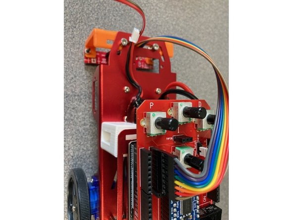
Use the 8-pin ribbon to connect the IR strip's sensors and the Arduino shield. The ribbon should not include the strip's pins for Vcc, Gnd, or LEDon, just the sensors 1 through 8. It should fit into the 8-pin shield header labeled "IR sensors output" with the wire for sensor 8 toward the back of the robot.
-
The ribbon can be tough to get on, but it will fit.
-
Use the 2-pin ribbon to connect the IR strip's power and ground to the Arduino shield. It should fit in the 2-pin shield header labeled "GND 5V".
-
-
-
Have the professor or TA verify your sensor strip is mounted correctly.
-
-
-
The QTR IR Reflectance sensor you will be using requires an Arduino library to be installed for it to work.
-
Go to Tools, select Manage Libraries, and then search "QTR". Install the one called "QTRSensors".
-
Download this sketch. It will be mostly filled out, so don't worry about initializations or the setup function.
-
-
-
You will be filling in the loop function for this code.
-
The first thing you will need to do is have the robot read the values from the sensor strip. Use this function:
-
reflect_snsr.read(sensorValues);
-
Note that the function is written to the array, "sensorValues". You may be tempted to print this out as you've done in past labs, but it won't work. Arrays are special and must be handled a bit differently than single variables.
-
-
-
To begin printing an array, start with a for loop that iterates from 0 to the number of sensors - 1. (If you look closely at the top of the code, you will see that there is already a variable for this)
-
Click here for the arduino reference to familiarize yourself with the required syntax for the C++ for loop.
-
The values of the array are in an element-by-element arrangement. Something like this: [a,b,c,d]. If we want to pick out a certain element from the array, we use its index, or its position (from 0 to 1-number of elements). For this example, the letter "c" has an index of 2, while "a" has an index of 0.
-
We can use an index to get the "n-th" element of sensorValues by writing it like this(remember that the first element is the "zeroth" element):
-
sensorValues[n]
-
Inside your for loop, print out the sensor values using the iterator as the index.
-
All 8 sensors should print out on the same line. Add a tab by printing '\t' between each value - Serial.print('\t')
-
Outside the loop, println a space so that the next set of data will start on a new line.
-
-
-
Have the professor or TA verify your data is printing correctly.
-
-
-
Now that your sensors are up and running, it's time to start looking at things.
-
You will be collecting data from the lab floor and from at least three types of tape: black and gray electrical tape and blue tape. These will be the line.
-
With the lab floor directly under the entire sensor strip, record the mean, median, range, standard deviation, minimum, and maximum of the whole set of sensor values for one reading (the sensor values might not be completely stable so if you have to approximate them, that's fine)
-
Repeat the measurements for the three lines, making sure they are under the entire sensor strip. Compare the results with the results from the floor. Which set of values stands out the most?
-
Adjust other parameters in your measurements. What other factors can affect your sensor readings?
-
-
-
Based on your collected data, pick a threshold value for when the sensor sees your chosen line against the floor. It must be high enough that the floor will never be detected, but also low enough that the line will always be.
-
Once you've picked your threshold value, go to the initializations in your code and set the threshold value.
-
Download this and copy it into the denoted space in your code.
-
That bit of code compares the sensor data to the threshold value to tell if the robot is looking at a line, and if so, it tells the robot where the line is.
-
For further clarification, here is a flowchart of that bit of code.
-
Move the robot such that the line is perpendicular to the sensor strip. If you move the robot so that the line is in different positions under it, the code will print out the line's position relative to the center of the sensor strip.
-
-
-
Have the professor or TA verify your robot is detecting the line's position.
-
-
-
Now that we have both the motor and sensor codes working, it's time to put them together and get the robot to follow a line.
-
Start by opening a new sketch. Copy your initializations and the contents of the setup functions of both your motor and sensor codes.
-
Copy only the loop function of your sensor code; none of the motor code loop function will be needed. Do, however, copy and paste the direction functions and runMotor functions themselves into the bottom of your sketch.
-
Do not actually copy the entire setup or loop functions as they are, but rather just the contents inside the braces. Be sure to skip repeats like the "Serial.begin".
-
-
-
Before you proceed, have the professor or TA verify that your code is structured correctly.
-
-
-
Download this piece of code. Copy it and paste it at the bottom of your loop function after the variable center is assigned a value and printed. Remove the delay(500) that was there.
-
Add an int variable "driveTime" to the other initializations, and set it to 50 for now. The aforementioned piece of code needs this to be able to run. Additonally, you will need to replace all instances of spd in that piece of code with whatever your speed variable is.
-
The wheels may not work correctly if "driveTime" is less than 50, so keep this in mind while adjusting parameters later.
-
This code contains the if-else statement structure that runs the auto-break and line-following systems.
-
The auto-break "turns on" when all or none of the sensors sees the line. This usually means that the robot is lost or is about run off the edge of a table. If either of those is the case, then stop moving (go forward with 0 speed). Else, follow the line.
-
The way the line-following works is that the robot looks at the variable center, and then turns or goes straight depending on its value. It drives in the determined direction for a specified amount of time in milliseconds (driveTime).
-
For each case of the line-following if-else statement, add a single line of code where indicated that calls a direction function such that the robot follows the line. Leave the rest as is.
-
If you get stuck, look back at your results from the Sensor Code lab. Look at the value of center as you move the line around.
-
-
-
Have the professor or TA verify that your directions are called correctly.
-
-
-
It's finally time for your robot to follow a line. Unplug it from the computer, place it on the line, and switch on the power. The robot might be super jittery, it might go for a bit then lose the line, or it might not even drive, just move back and forth over the line.
-
There are a few parameters you can adjust to optimize your robot's driving. They are the threshold, your speed variable, the turn ratio, the off-wheel direction, and drive time.
-
Adjust each of these parameters individually and write a brief description of the effect they have on the way the robot drives.
-
Keep adjusting and testing until your robot is able to follow the test track. Try out the auto-break as well.
-
Write a short paragraph about your process for adjusting and testing the robot. Which adjustable parameter was the most challenging to configure? What are your final parameter values? How long did it take until you generally succeeded at getting your robot to follow a line?
-
-
-
Once you feel your robot is able to follow the whole track, demonstrate to the professor or TA.
-
-
-
Now that your robot can successfully follow the line, let's see how fast you can make it go! Optimize your code so that your robot can complete the course quickly. You can continue to optimize the adjustable variables but can also change the structure of the code for this step.
-
Time your robot completing the course. The fastest groups will get a 10% bonus on this week's lab grade!
-
What strategies did you try to make your robot follow the line faster? Describe the strategy that was most successful.
-
-
-
Now that the robot can perform its intended functionality, it's time to add further applications.
-
You will be using the speed potentiometer and an input from another sensor in addition to the IR reflectance strip.
-
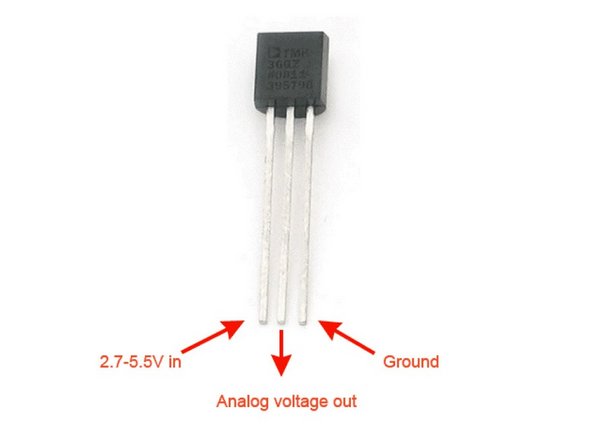
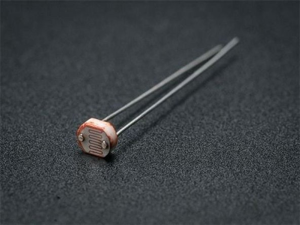
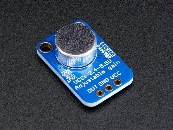
We have 4 sensors available in the lab that you can choose from: Light dependent resistor (LDR); Analog temperature sensor (TMP 36), a Hall effect sensor (SS445P) or a microphone amplifier ( MAX 4466).
-
You will be writing a new set of directions for your robot that use the output of a new sensor and at least one of the available potentiometers.
-
For example, if my robot is driving along and detects a sudden increase in temperature, it would know that it has overheated and will drive in a circle until it cools off.
-
Now, that was a silly example. What you choose to have your robot do will be up to you. You will have access to small magnets to use with the Hall effect sensors and hair dryers to adjust temperature for the temperature sensors.
-
-
-
Spend about 5 minutes coming up with an idea for an application for your robot. Once you have something, have the professor or TA approve it.
-
Here are the constraints for your application:
-
The robot still must show the ability to follow a simple line.
-
The application must use the output of a new sensor.
-
The application must also use at least 1 of the 3 available potentiometers to adjust something.
-
-
-
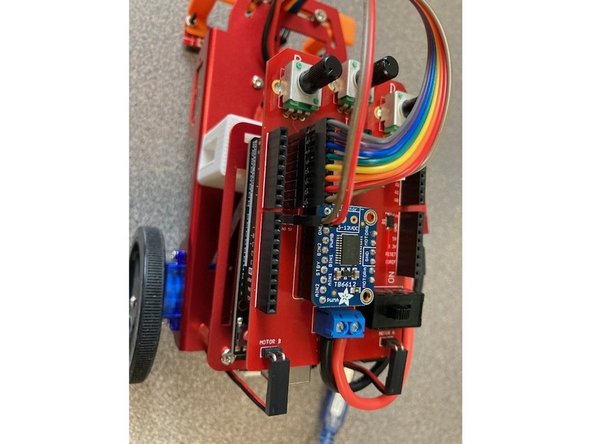
The additional sensor will need to be connected to the 3-pin header near the center of the shield.
-
The temperature sensor can be inserted directly into the 3-pin header with the flat of the sensor facing the back of the robot.
-
To use the LDR, you will need to include a resistor to make a voltage divider. Twist one end of the LDR and resistor together and insert it in the middle of the 3-pin header. The other ends go into power and ground, just be sure to use the appropriate orientation when calculating the voltage.
-
To use the Hall effect sensor or the microphone, male to female jumper wires should connect the sensor pins to the header on the robot shield.
-
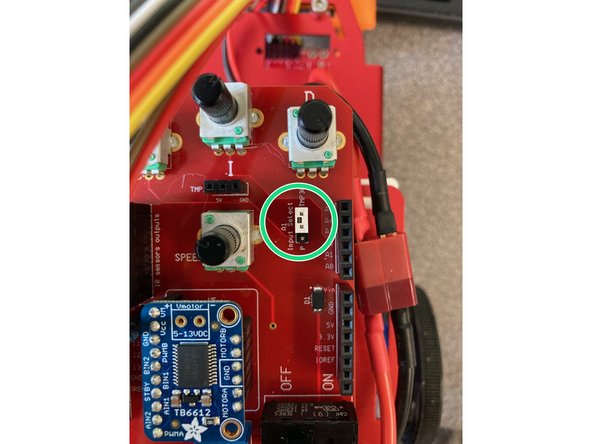
When using the 3-pin header with any sensor you will need to be sure that the white jumper (green circle) on the 3- pin male header is connecting A1 to the analog input and not the potentiometer.
-
The speed potentiometer is connected to A0. You must use this as an input of some sort.
-
-
-
After connecting your sensor, update your code so that it will read the sensor value and print out the result to the serial monitor.
-
Vary the conditions and observe the output of your sensor. If your application requires a threshold, determine an appropriate value.
-
Demonstrate the functionality of your sensor to the professor or TA.
-
-
-
Modify your code so that it will read and use the value output by a potentiometer.
-
Test the functionality of the potentiometer - show that you can adjust your robot's operation by varying the potentiometer's position.
-
Demonstrate the potentiometer's functionality to the professor or TA.
-
-
-
Once you have successfully implemented your full application, demonstrate it to the professor or TA.
-
Upload your final code as a .ino file to the designated space on Gradescope.
-
-
-
Write a paragraph documenting your process of figuring out an application, implementing it, and testing it. Did you have a clear picture of your end goal? Did you have to change your approach along the way?
-
-
-
Think back over the whole process including building, programming, testing, and finally, designing an application for your robot. What were some things you learned? Write a couple paragraphs summing up your experience.
-


Cancel: I did not complete this guide.
2 other people completed this guide.
Team
2 Comments
I thought this tutorial was extremely helpful. The step by step approach with pictures and code integrated into the directions really helped with both the building process and our understand of the system. If there is one thing I could change, it would be to have an STL of the sensor mount already loaded into the tutorial. It seemed like most groups, including my own, simply recreated the mount on the example vehicle. Evidently, there were not many design choices to really make, limiting the individuality of the designs. As we were printing the night before the lab that needed this bracket printed, I kept wondering what a group with an inadequate bracket would do. Would they simply not be able to complete that week's portion of the project? I think a lot of worrying and troubleshooting could be avoided with a STL. - Jamie, Ethan & Mert
Jamie Lickstein - Resolved on Release Reply
Overall the layout worked pretty well and was easy to follow. One thing I would suggest is that we had a problem every time we would download code, it would make it impossible to get back to the guide and we would have to reopen everything. I don't know if that is a program error or device error, but the problem arose on my mac and the lab computers - Jesse & George
jesse choate - Resolved on Release Reply