Introduction
A Field Effect Transistor (FET) is a device that can control the flow of electricity based on the voltage input an its gate pin. In this tutorial you'll learn how to use an FET as a switch to control large amounts of power with a voltage from a microcontroller. If you want to read more about FETs, here is a good introduction.
Tools
Parts
No parts specified.
-
-
The kit contains a 10 Kohm resistor (color codes), a a small signal N-channel MOSFET, two red LEDs, and a Circuit Playground microcontroller to turn the LEDs on and off.
-
There are other FET transistors available that will handle more power if you want to drive a device like a motor, but this tutorial uses a smaller transistor to light two LEDs.
-
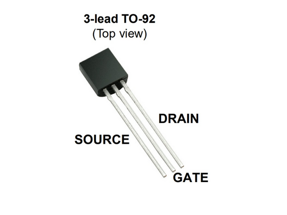
The link in the first step goes to MakerStock. You can download the datasheet by clicking on "Fairchild Semiconductor 2N7000BU". The critical part of the data sheet is shown in the second image.
-
It is always a good practice to have the datasheet for any electronic parts you are using handy.
-
The kit also contains a breadboard, some hookup wire, and a USB cable to power the microcontroller.
-
-
-
The first circuit we'll set up on a breadboard drives the LEDs directly using the output of the microcontroller. Wire it up as shown in the first image.
-
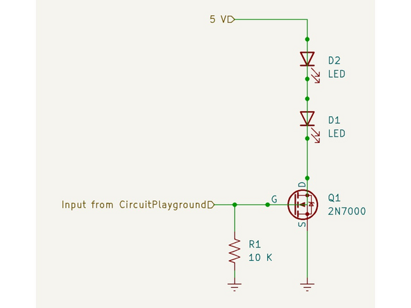
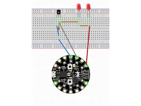
Build the circuit shown in the pictures on the breadboard. One of the pictures is the schematic view and the other shows how to hook up the circuit on a breadboard.
-
It matters which way the LEDs are wired up. On the bullet-shaped case there is a flat side near one of the pins. That flat side corresponds to the line in the schematic diagram, and has a shorter pin. The other, longer pin corresponds to the arrow and is the anode (anode-arrow).
-
Make sure to put the LEDs in so the longer pin goes to the positive voltage side, away from ground.
-
-
-
When you have double checked the wiring, plug in the USB cable to power up the circuit. It may take a moment to start.
-
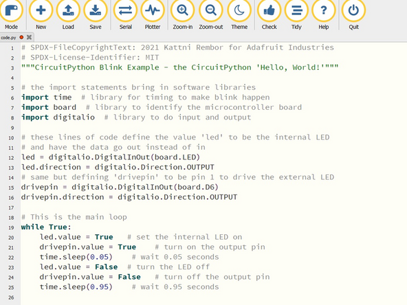
If the light on the Circuit Playground doesn't blink it may be the code was changed. You can download the code.py file from this drive site and copy it onto the Circuit Playground.
-
You should see a red LED on the Circuit Playground flash at about a 5% duty cycle (0.05s on, 0.95s off).
-
The two LEDs on the breadboard will flash very dimly since the output voltage from the pin is not high enough to drive them as shown in the video.
-
If the two LEDs don't flash make sure they are inserted the right way and they are connected to output A1 of the Circuit Playground
-
-
-
Next we'll wire up the FET as a switch, using the output signal from the microcontroller to drive the gate, turning on and off the LED.
-
Be aware transistors are complicated devices. In this tutorial we are using it in a very simple way.
-
Hook up the transistor exactly as shown. It has three pins - a gate, source, and drain - and the circuit won't work if you have them hooked up incorrectly.
-
What the NMOS FET does is act like switch so that when a voltage is applied to the gate, larger amounts of current can flow between the source and drain (the terminals of the 'switch') to make the LED brighter.
-
The resistor help make sure the gate stays at ground, or 0 volts. Since the input is high impedance stray electric fields can turn the device on if this part isn't there.
-
We will use the 5V output of the Circuit Playground to drive the LEDs. This is labelled VOUT.
-
Hook up the + and - terminals as shown in the diagram.
-
-
-
Double check your connections then power up the microcontroller board using the USB connector.
-
Here instead of driving the LED from the 3.3V output of a pin that has limited current, we are putting 5V with no current limit into the LEDs through the FET.
-
Because the LED is only on for a short amount of time, it won't be damaged by this amount of current. If it was going to be on longer we would put a resistor in series with the LED to limit the current!
-
This handy calculator is useful to determine the current limiting resistor you need for a given LED.
-
If you hooked up the circuit correctly you should see both LEDs flashing much more brightly because of the power we can supply using an FET.
-
If the LEDs aren't flashing double check that you wired the circuit correctly, the LEDs are in the right direction, and you have the S, D and G pins of the FET wired correctly.
-
-
-
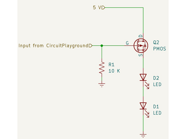
We used an NMOS FET for our driver circuit but there are also PMOS FETs. They work the same way but the circuit is slightly modified as shown in the schematic diagram.
-
You need to choose the specific FET transistor for your project based on the amount of power you need to provide to the load.
-
There are many different variations of this basic circuit. For example a device called an H-bridge can be used to vary motor speed in forward and reverse directions.
-
You can also use this circuit to vary the power to a load (for example dimming a light or controlling a servo) by using a technique called pulse width modulation.
-
Woot, you have completed the FET driver tutorial and added another skill to your toolbox.!
-
-
-
To earn the FET driver badge you'll need to do two things:
-
1) Rebuild the driver using a PMOS rather NMOS transistor. The BS250P is available from MakerStock.
-
2) Change the code to variably adjust the brightness of the LEDs based on the input of a potentiometer. This will show you how to use pulse-width modulation (PWM). You'll need to use much shorter on and off times than the previous code.
-
You will have to set up the potentiometer as a voltage divider and read the input voltage using an analog pin.
-
After completing the challenge please put the original code.py file on the Circuit Playground. The code is in this folder.
-
Drive a Load with an FET transistor: Quiz


