
Introduction
Note that the maximum dimensions of any sample imaged on the SU5000 are:
- 200mm diameter
- 80mm depth
Tools
No tools specified.
Parts
-
-
Note that the maximum dimensions of any sample imaged on the SU5000 are:
-
200mm diameter
-
80mm depth
-
We use brass disks to mount samples because the disks can be removed from the sample holder without disturbing the specimen. Thus specimens once mounted can be imaged again in the future if necessary.
-
Apply a strip or dot of the Double Sided Carbon Tape to one face of Brass disk.
-
Place your specimen on the tape. For larger specimens, press the specimen into the tape. For Powders, use the provided compressed air to blow excess powder off the disk. For powders you are not recovering, blow excess into the garbage.
-
If sputter coating, now is the time to do so; otherwise proceed to the next step.
-
-
-
Apply a dot of Double Sided Carbon Tape to sample holder.
-
Peel paper backing from tape.
-
Press Brass disk with sample onto sample holder.
-
-
-
No food or drinks in the lab
-
No unauthorized visitors in the lab.
-
There are two labs accessed by walking though the SEM room, please keep the area tidy and free of tripping hazards
-
Parts of the apparatus run at HIGH voltages. Do not touch anywhere except controls.
-
Do NOT attempt to examine magnetic samples with the SEM. Magnetic samples are likely to break free of the specimen holder and be accelerated into the detector causing damage to the apparatus.
-
-
-
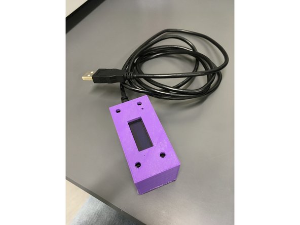
Connect the Magnetometer found in the lab to a PC using the USB A to Micro B cable to provide it with power.
-
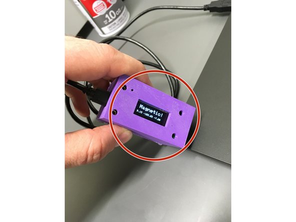
We have set the magnetometer to be fairly sensitive. In some locations in the lab it can read "MAGNETIC" simply by the combination of Earth's magnetic field and the magnetic fields surrounding the electrical supply lines in the wall. Insure that it is not reading "MAGNETIC" to start.
-
If you have a laptop handy, you can test the magnetometer as most laptops have a small magnet along one edge to sense if the lid is closed.
-
Move your Sample near the end opposite of the USB cable. If the magnetometer reads "MAGNETIC"... STOP! DO NOT PLACE IT IN THE SEM.
-
-
-
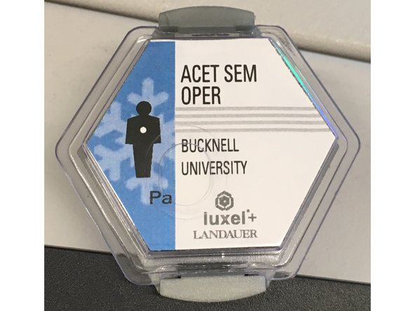
In order to comply with state regulations for equipment which produce X-Rays when in operation we log who uses the apparatus and have placed dosimeters inside and outside the laboratory which are regularly checked by Bucknell EH&S
-
Please do not touch or place hot objects near the dosimeters as that may cause them to record a false positive.
-
You will need a Bucknell Equipment Activation card to activate the SEM such as the cards used in the Bucknell Makerspaces. Contact egsem@bucknell.edu if you need a card issued to you.
-
-
-
Sign on to the PC using your Bucknell logon. Only authorized users will be permitted to sign on. Remember to sign off when done.
-
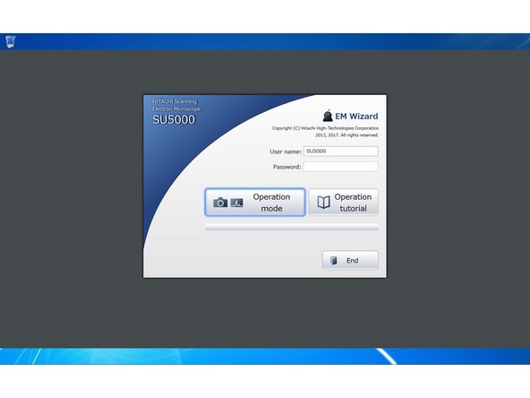
You will use the application "EM_Wizard" to control the SEM and capture images. EM_Wizard should open automatically when you logon, if not, launch EM_Wizard by double clicking the icon on the desktop.
-
At the splash screen / login page, press the enter key to go to the main window.
-
-
-
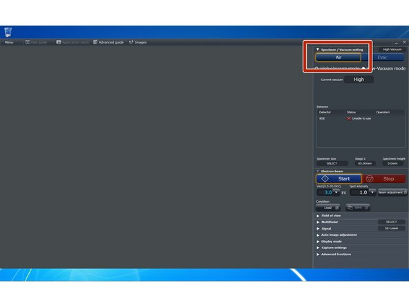
The sample chamber is kept under vacuum when not in use to maintain the condition of the equipment.
-
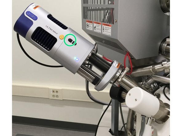
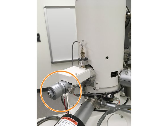
Be sure that the EDS/EDX detector is in the extended (removed from sample chamber) position before venting the chamber.
-
Click the "Air" button under the "Specimen / Vacuum setting" section of the sidebar to vent the sample chamber
-
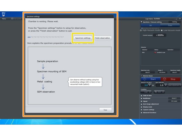
The software will open a modal window titled "Specimen settings" and make a soft series of beeps when the chamber pressure has equalized with the room.
-
While waiting for the chamber to equalize with the room pressure, you may click the "Specimen Settings" button to start the specimen setup process.
-
If warned about replacing the thumbnail, click "Ok", we will be generating a new one of your sample in a few steps.
-
-
-
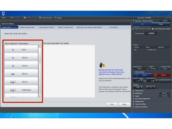
Choose the size of your sample mounting disk. Typically you will use 26mm, the diameter of the brass disk. If you have a different size mount you should use that if it appears in the list. If none of the choices are an exact match, choose a size larger than the disk your sample is mounted to. Click "Next"
-
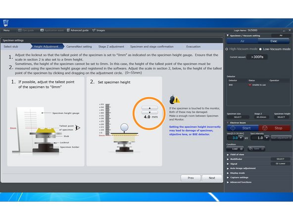
Adjust the stage offset height by entering the height of your sample mounting assembly from step 4. Click "Next".
-
-
-
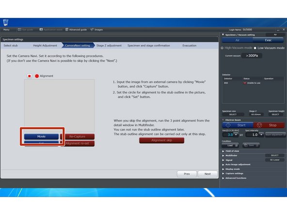
Insert the specimen holder assembly into the NaviCam so that the mount is snug against the stop bar. Turn on the Navicam light.
-
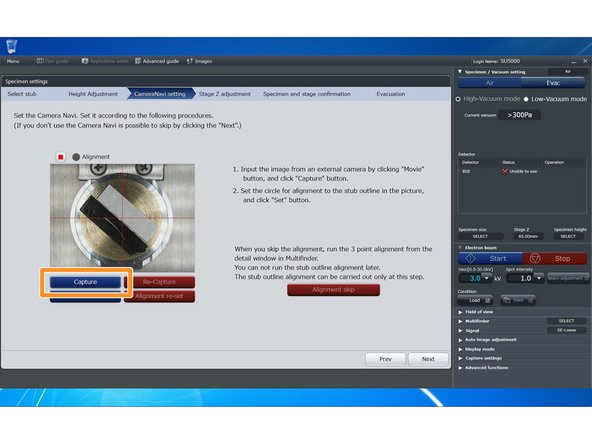
Click the "Movie" button to get a live preview of your specimen.
-
Click the "Capture" button to take a still image of your specimen.
-
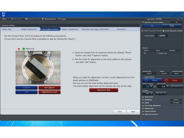
Drag the straight lines to position the circle around the top of your sample holder.
-
When satisfied, click "Set" to set the thumbnail and then the "Next" button to proceed.
-
-
-
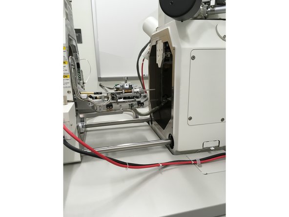
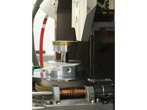
By this point the software should have beeped and you can slide the sample chamber all the way open.
-
Slide your sample holder assembly onto the stage.
-
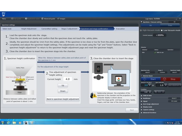
Partially close the specimen chamber. You want your specimen to clear the equipment guard by around a millimeter but two millimeters of clearance is better than none.
-
If your sample is too close to the guard, pull the chamber all the way open again and use the software to adjust your sample height.
-
When you have the proper clearance, slide chamber all the way closed and click "Next" in the software.
-
-
-
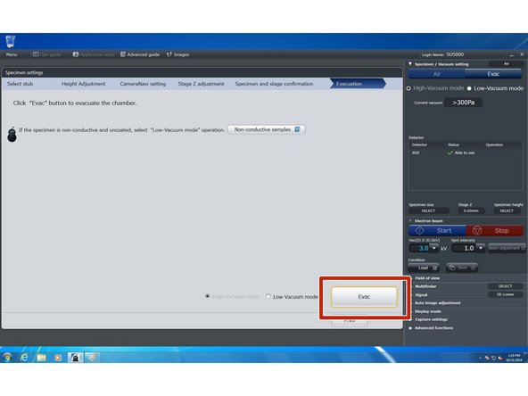
You are now ready to evacuate the chamber. "High vacuum mode" is used in most circumstances. Click the "Evac" button to start emptying atmosphere from the chamber.
-
While waiting for the chamber to achieve a vacuum, check your starting aperture. For low energies <= 5 kV you should start with an aperture of 4.
-
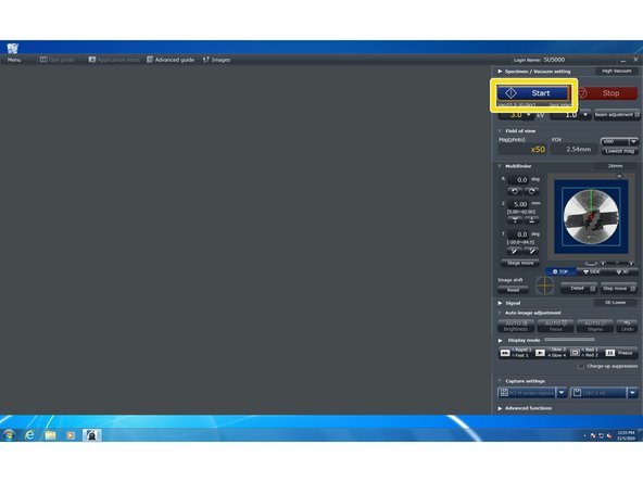
Once the chamber has reached a vacuum, you can engage the beam. Good starting settings for the beam are an energy of 3kV and a spot size of 1.0.
-
Click "Start" to start the beam.
-
-
-
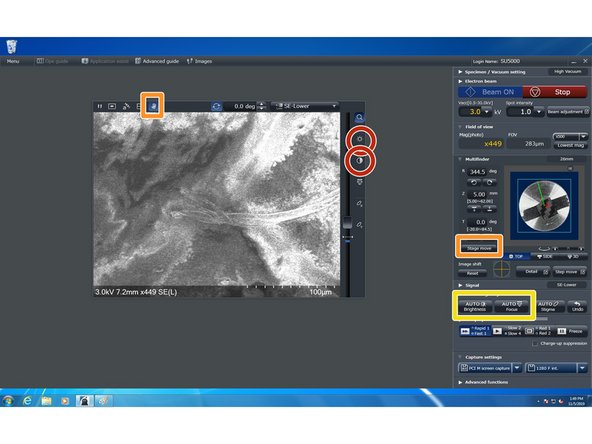
Once the beam is running, an image window will appear in the EM_Wizard window.
-
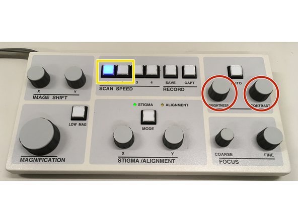
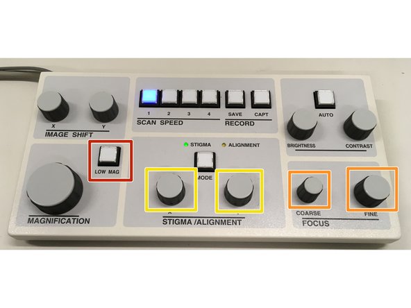
You can adjust the brightness and contrast of the image using either the sliders in the image window or the knobs on the control deck.
-
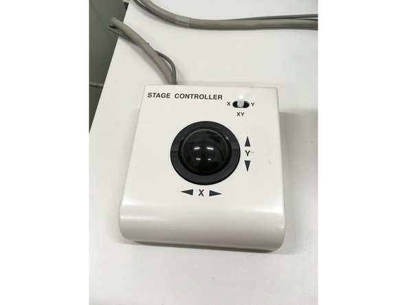
You can move around your sample using the trackball, the thumbnail and stage move button in the EM_Wizard control sidebar, or using the navigation tools in the image window.
-
You can also change scan speed using the buttons on the control deck and in the software. "Fast" scans have more noise, but the beam passes over the sample more rapidly reducing charge buildup and refreshing the image more often. "Slow" scans have less noise but may charge your sample and refresh too slowly when adjusting focus etc.
-
-
-
Focusing the apparatus to obtain a crisp clear image of your specimen can be a bit of an art. Be patient, it takes a bit of practice. Also ask for help if you can't get an image.
-
You have the option of using either the control deck or the software interface for this task.
-
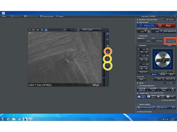
It is often helpful to start by reducing the magnification to the minimum. Most users find it easiest to focus while in "Fast" display mode.
-
Use the coarse focus knot first then the fine focus knob on the control deck or the focus slider in the software to make edges in the image on screen as defined as possible. Then step up your magnification an order of magnitude and repeat until you are have focused the image at a magnification twice that at which you intend to acquire images.
-
If you have reached a point where you can not seem to get anymore definition to you image, you may try the stigmators.
-
If however the image is sliding around as you focus and/or stigmate, you may have a beam alignment issue. Do the best you can but once you have increased the magnification so far that the image is sliding dramatically as you focus you should proceed to the next step "Beam Alignment" and after aligning the beam, return to this step.
-
Once you have focused your image, you should move on to Image Capture.
-
-
-
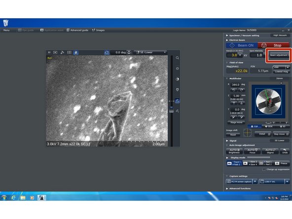
Start the beam adjustment process by clicking on the "Beam adjustment" button.
-
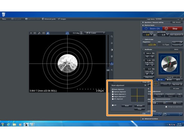
It is important to perform the "Beam Alignment" before "Aperture Alignment" and "Aperture Alignment" before either "Stigma alignment" but X and Y Stigma alignment can be performed in either order.
-
The "Beam Adjustment" window will open; by default, "Beam Alignment" will be selected. Use the Stigma/Adjustment X and Y knobs on the control deck to center the circle.
-
When centered, click the radio button for "Aperture Adjustment". The circular image mask will be removed and the image may be sliding around. Use the Stigma/Adjustment knobs on the control deck to minimize the motion. Ideally, the image will be pulsing a bit like a balloon inflating and deflating.
-
Click the radio button for "Stigma alignment X". Again the image may be sliding around, Again you want to minimize the sliding using the Stigma/Adjustment X and Y knobs.
-
Click the radio button for "Stigma alignment y". Again the image may be sliding around, Again you want to minimize the sliding using the Stigma/Adjustment X and Y knobs.
-
"AFC [Auto Focus Contrast] alignment" has no effect on imaging and can be skipped.
-
-
-
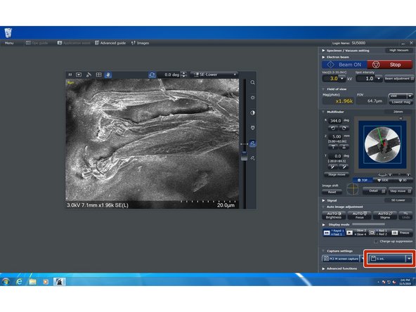
When you have found the region you want to image and focused the image you are ready to capture your image. EM_Wizard supports a number of capture modes. Most users should switch to slow scan, then click the button with the floppy disk silhouette. Note: the text on this button is variable but is typically "1280 S".
-
A customized save dialog will appear and you can choose where to save your image and what to name the image.
-
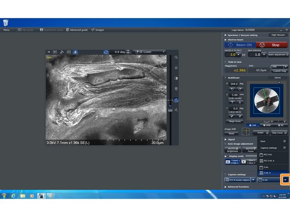
For those wanting to do measurements of features in captured images you can send the captured image to "Quartz PCI" by clicking on the "Save Extras" menu and choosing the "PCI..." save option then clicking the capture button.
-


Cancel: I did not complete this guide.
7 other people completed this guide.
