
-
-
AutoCAD is a common CAD software and was really among the first CAD programs that was widely used. It is a professional software package, has great support, and like many such packages has the advantage that there are lots of help resources and tutorials and a larger user base.
-
Like other commercial software packages used professionally, one of the obstacles for beginners is that there are a huge number of options and can it take a long time to learn. It is also expensive.
-
If this is a concern here is a listing of free CAD packages: Free CAD packages
-
This really brief tutorial is only going to cover a few of the many commands available to create a two dimensional object. These commands can basically be divided into three categories: 1) Setting up AutoCAD, 2) Drawing Objects, 3) Changing Objects
-
If you want to learn more about the commands you might want to open a site with more information like this one to have open while you do the tutorial.
-
-
-
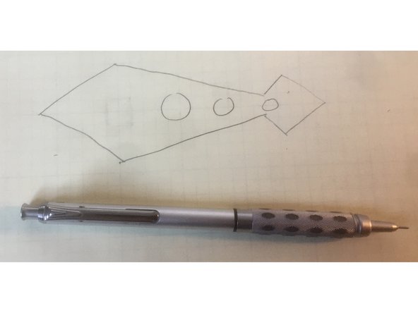
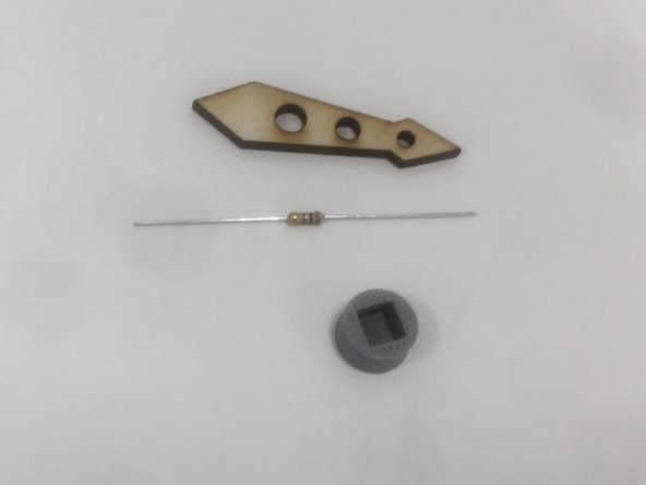
The tutorial is going to walk you these topics in order by having you create a 2D object, the arm for the programmable display device you can laser cut. This is shown in the photo, and will be pretty small, smaller than the length of a resistor.
-
As with some of the other tutorials it is going to be very linear, and show you commands for a specific goal rather than teach the commands and let you figure out how to use them. At the end of this brief tutorial are links to resources if you’d like to learn more about using AutoCAD and also a little bit about how to take a 2D object in to 3D.
-
Note that SolidWorks is generally better at 3D CAD, and we have a tutorial on this site.
-
-
-
Set up the cursor - right click, and in the popup menu select options at the bottom, then click on the display tab. When you are in the Display tab slide the crosshair size slider to 100%. This is helpful in aligning parts.
-
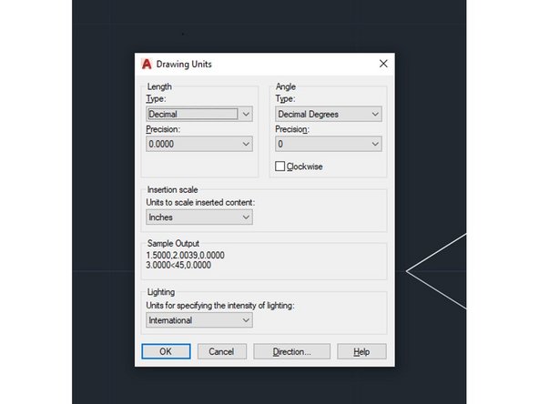
Set the units - you can use the mouse to select commands in AutoCAD, but it is really designed to type commands (and this is much faster). Type “units” and hit the carriage return. Don’t change anything, but this is where you would set up different units if you needed to. Hit cancel to exit.
-
Set the snap - if snap is on the cursor will make discrete jumps for a given distance. If snap is off the cursor moves smoothly. Turning snap on can be useful to avoid crooked lines and to make sure alignment is correct. Types “snap .05” which will set the snap to 0.05 inches since our units are in inches.
-
The F9 key toggles snap if you need to turn it on and off.
-
-
-
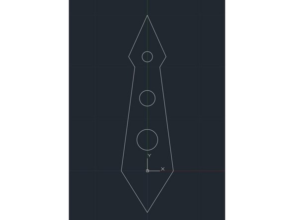
We are going to make a diamond shaped pointer with some circles down the axis as shown in the figure below. This was my rough sketch drawn on engineering paper to get an idea of what I wanted.
-
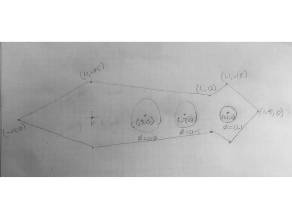
To create this object we are going to specify coordinates in a cartesian space centered on (0,0) then make the outline of the pointer by specifying each point as an (x,y) coordinate. Below is the drawing with each point specified.
-
Note that while I used pretty easy numbers on most of the coordinates for the square hole in the middle I have to adjust the number I want (0.125” since the magnet on the motor is 0.25” square) by the cutting width of the laser beam which is 0.014” diameter or 0.007” radius).
-
The point to be made here is that you'll need to determine the coordinates of each feature in your drawing before you start AutoCAD.
-
-
-
Here is the hand drawing with with coordinates of the top points. The easiest way to create a precise object in AutoCAD if you are a beginner is to know each coordinate point of your object.
-
If you are going to create an object as a CAD beginner it is helpful to know the coordinates of each point in the 2D object you'd like to draw.
-
-
-
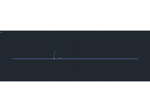
AutoCAD is hard to work in if you are zoomed too far in or too far out. So to get an idea of the size of our object we’ll first draw a line from the point (-1,0) to (2,0) so that we know how much to zoom in. Type “line” and hit enter, then when it asks you to specify the first point type “-1,0” and hit enter.
-
For the second point type “2,0” then hit enter. Hitting enter one more time exits the line command.
-
Now zoom in by typing “zoom”, enter, then “w”, enter to zoom to a window on the screen. You can also use your mouse wheel which zooms in and out around the point the cursor is at. Make a window so the line is about 50% of the width of the window. Play around with this to practice zooming in.
-
If you type "pan" then hit enter you'll see a hand and can drag the drawing around to center the line on the screen as shown. Hit "escape" to exit pan.
-
Note if you get lost you can type “zoom”, enter, “a”, enter to zoom to all the drawing.
-
-
-
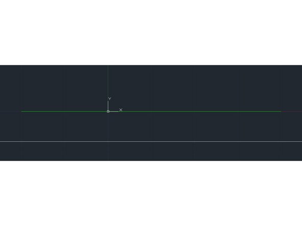
Now we have the center line of the pointer. We’re not going to use this as part of the drawing so lets change it to be a green line so it stands out. Type “change” then click on the line and hit enter. The line turns bluish as shown. When AutoCAD prompts you specify the point type “p” then hit enter to get to the properties menu.
-
We want to change the color so type “c” (from now on when I say type something I am going to assume you hit enter right afterwards and not type enter any more).
-
Now type “3” to change the color to green (then hit enter again). 1 = red, 2 = yellow, 3 = green, 4 = cyan, 5 = blue... Hit enter again and you should exit the change command and see the line turned green as shown in the second image.
-
-
-
It may be that your line goes from (-1,0) to (1,0) rather than to (2,0). In other words it is 2" rather than 3" long.
-
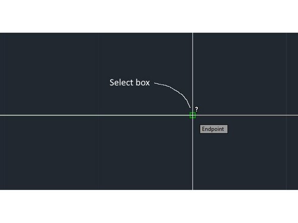
We can measure the length with the distance command. Type "dist" then enter. Click on the left then the right ends of the line. A small green box will appear when you are close to the end and the cursor should snap into place. See the box on the image.
-
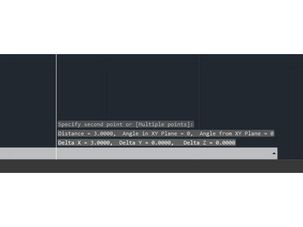
After you click on the end of the line you'll see distance information down on the bottom of your screen as shown in the second image.
-
If your line is only 2" long then you are in relative coordinate mode where you enter the relative distances from the last point rather than absolute coordinate relative to the origin.
-
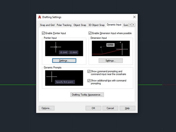
To fix this do the following: On the command line, type “dsettings”. You will see the dialog box in the third image appear. In the Dynamic Settings dialog box, click the Dynamic Input tab. Under Pointer Input, click Settings. In the Pointer Input Settings dialog box, select Absolute Coordinates.
-
You can accomplish the same thing by hitting F12 once to switch between relative or dynamic coordinates. Once you get out of relative mode redraw the box.
-
-
-
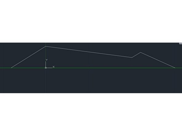
Now we want to draw the top half of the pointer. We’ll use the polyline or pline command for this. Type “pline” then enter the first of the five coordinates which is (-.4,0). To do this type "-.4,0" then hit enter.
-
Next enter the remaining four coordinates: (0,.25),(1,.12), (1.1,.18), (1.5,0). Do it the same way by typing the x then the y coordinate pair, then hit enter a final time to exit the pline command.
-
Note that while we don’t go into this here, there are options on the pline command that will let you draw arcs, lines of different thickness, and otherwise customize the shape. Feel free to play with this to customize the shape of your pointer. More here.
-
You should have something that looks like the image.
-
-
-
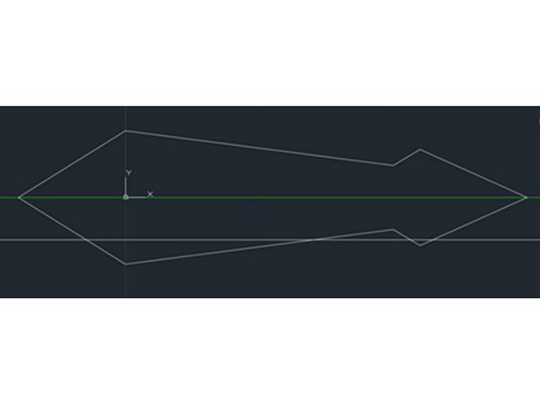
Now we have designed the top half of the pointer. We could do the same for the bottom half, but there is an easier way. We’ll use the mirror command to mirror-image the top onto the bottom. Type “mirror” and use the cursor to select the polyline (but not the green center line) then hit enter.
-
Now you have to select the line around which the object should be mirrored, that is the green center line. Remember little green autoselect boxes should pop up and the cursor should snap in when you get close. Click at one end of the green line and then the other.
-
This should mirror the pointer so it is complete. AutoCAD wants to know if you want to remove the top half, type “n” for no so AutoCAD does not remove the top part.
-
If you screw up here typing “u” will undo the last command. Keep typing “u” or just hitting enter and you can go back and undo multiple commands.
-
The image shows what you should have now.
-
-
-
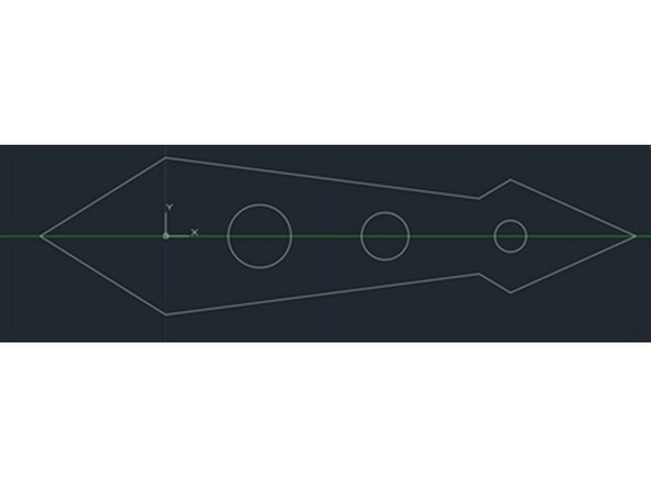
Now let’s add some aesthetic holes at points (.3,0), (.7,0), and (1.1,0) along the axis. The diameter of the holes will be 0.2”, 0.15”, and 0.1” respectively.
-
Type “circle” and enter the first set of coordinates for the center of the circle (.3,0).
-
The circle by default wants you to enter a radius so hit “d” for diameter then enter the first diameter of 0.2. Alternatively you can not type "d" and entire the radius which is 0.1.
-
Repeat for the other two circles. Your figure should look like the image.
-
-
-
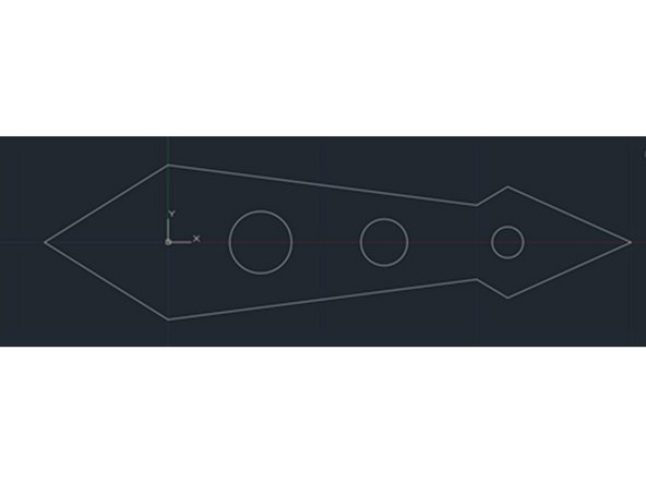
All we have to do is erase the green center line and we’re done! Type “erase” then select the green line and hit enter.
-
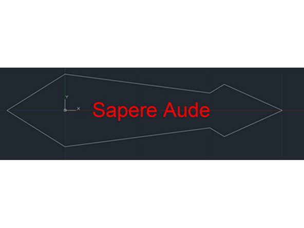
If you don’t want to make the circles, you might look at the “dtext” command to put writing on your pointer. Note that you have to make the text a different color using the “change” command so you can change the laser power to etch rather than cut the shape.
-
The second image is what I got when I used “dtext” with a text height of 0.1”, then used the “move” command to get the text where I wanted, and the “change” command to change properties to color to 1 which is red.
-
When you laser cut objects with different colors will have different laser settings so I changed the color so I could set the laser cutter to etch rather than cut.
-
-
-
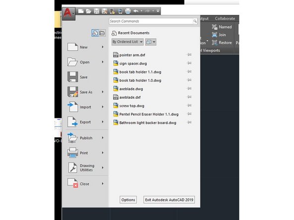
Go to the big red A in the upper left corner and save your file first as a AutoCAD .dwg file. If you need to edit your work later you can open this file and make changes.
-
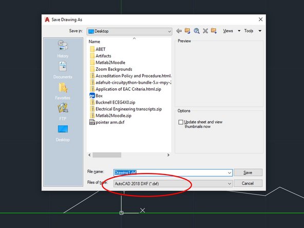
Next Save As then select “AutoCAD 2018 DXF”. DXF stands for Drawing eXchange Format and this file type can be imported by the laser cutter.
-
The laser cutter tutorial describes how to import .dxf files.
-
-
-
Now that we have the file saved it is worth playing around with some ways to change objects...
-
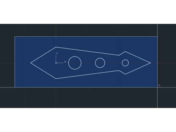
Type “rotate” then type “w” so you can select objects by a window.
-
Click twice at the lower left and upper right corners to make a window big enough to select all the objects and hit enter to select them. It should look like the first figure.
-
Now AutoCAD will ask the point the object will be rotated aroud, click on the origin as the rotation point. Now type “90” to rotate the pointer by 90 degrees. You should see something like the image.
-
Type “u” to undo the rotate. Now type “move” and select one of the circles and hit enter. Select the base point at the center of the circle by clicking near the center with your mouse
-
Experiment with the “copy” command that works the same way.
-
-
-
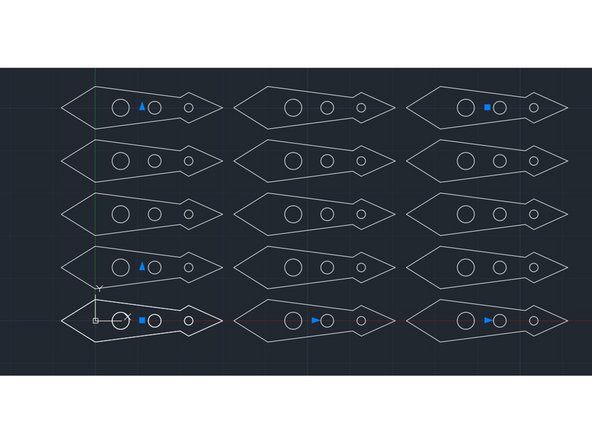
If we wanted to make a lot of the pointers we can use the array command to make many.
-
Type “array”, then “w” to select all the objects by window.
-
Select “r” for rectangular array.
-
Use your mouse wheel to zoom out and grab one of the blue symbols with your mouse. By dragging the various you can change the spacing and number of objects in the array.
-
-
-
If you want to make a 3D object you can easily modify this design in AutoCAD. It is always faster to laser cut than to 3D print, but once you have the file saved look at the “extrude” and “subtract” commands in AutoCAD.
-
Finally from the big red A you can choose to export the file as .stl which can be 3D printed.
-
That is probably enough for now. This tutorial was not meant to be comprehensive since there are a *lot* more AutoCAD commands and you can find them through many on-line tutorials.
-
Here is another link to a tutorial if you would like to learn more.
-


Cancel: I did not complete this guide.
4 other people completed this guide.
